SECTION 7
CESSNA
AIRPLANE & SYSTEMS DESCRIPTIONS
MODEL 172RG
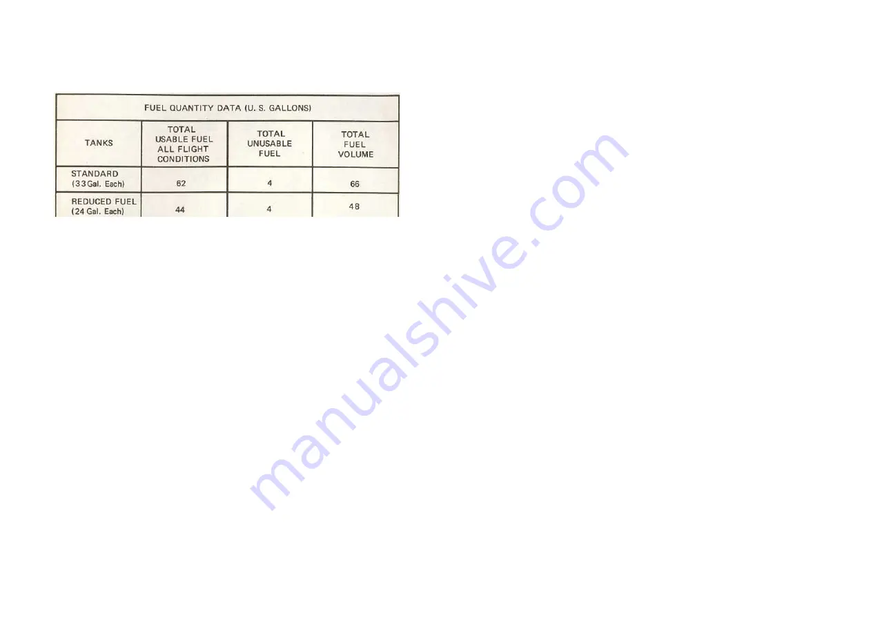
Figure 7-6. Fuel Quantity Data
NOTE
Unusable fuel is at a minimum due to the design of the fuel
system. However, with 1/4 tank or less, prolonged uncoor-
dinated flight such as slips or skids can uncover the fuel
tank outlets, causing fuel starvation and engine stoppage.
Therefore, with low fuel reserves, do not allow the airplane
to remain in uncoordinated flight for periods in excess of
30 seconds.
NOTE
When the fuel selector valve handle is in the BOTH
position in cruising flight, unequal fuel flow from each
tank may occur if the wings are not maintained exactly
level. Resulting wing heaviness can be alleviated gradu-
ally by turning the selector valve handle to the tank in the
"heavy" wing.
NOTE
It is not practical to measure the time required to consume
all of the fuel in one tank, and, after switching to the
opposite tank, expect an equal duration from the remain-
ing fuel. The airspace in both fuel tanks is interconnected
by a vent line and, therefore, some sloshing of fuel between
tanks can be expected when the tanks are nearly full and
the wings are not level.
If a fuel tank quantity is completely exhausted in flight, it is recom-
mended that the fuel selector valve be switched back to the BOTH position
for the remainder of the flight. This will allow some fuel from the fuller
tank to transfer back through the selector valve to the empty tank while in
coordinated flight which in turn will prevent fuel starvation when operat-
ing in prolonged slips or skids.
7-26
1 July 1979
CESSNA
SECTION 7
MODEL 172RG
AIRPLANE & SYSTEMS DESCRIPTIONS
The fuel system is equipped with drain valves to provide a means for
the examination of fuel in the system for contamination and grade. The
system should be examined before the first flight of every day and after
each refueling, by using the sampler cup provided to drain fuel from the
wing tank sumps and selector valve, and by utilizing the fuel strainer
drain under an access panel on the right side of the engine cowling. The
fuel tanks should be filled after each flight to prevent condensation.
HYDRAULIC SYSTEM
Hydraulic power (see figure 7-7) is supplied by an electrically-driven
hydraulic power pack located behind the firewall between the pilot's and
copilot's rudder pedals. The power pack's only function is to supply
hydraulic power for operation of the retractable landing gear. This is
accomplished by applying hydraulic pressure to actuator cylinders which
extend or retract the gear. The hydraulic system normally operates at 1000
PSI to 1500 PSI, and is protected by relief valves which prevent high
pressure damage to the pump and other components in the system. The
electrical portion of the power pack is protected by a 30-amp push-pull
type circuit breaker switch, labeled GEAR PUMP, on the left switch and
control panel.
The hydraulic power pack is turned on by a pressure switch on the
power pack when the landing gear lever is placed in either the GEAR UP or
GEAR DOWN position. When the lever is placed in the GEAR UP or GEAR
DOWN position, it mechanically rotates a selector valve which applies
hydraulic pressure in the direction selected. As soon as the landing gear
reaches the selected position, a series of electrical switches will illuminate
one of two indicator lights on the instrument panel to show gear position
and completion of the cycle. After indicator light illumination, (GEAR
DOWN cycle only), hydraulic pressure will continue to build until the
power pack pressure switch turns the power pack off.
The hydraulic system includes an emergency hand pump to permit
manual extension of the landing gear in the event of hydraulic power pack
failure. The hand pump is located on the cabin floor between the front seats.
During normal operations, the landing gear should require from 5 to 7
seconds to fully extend or retract. For malfunctions of the hydraulic and
landing gear systems, refer to Section 3 of this handbook.
BRAKE SYSTEM
The airplane has a single-disc, hydraulically-actuated brake on each
main landing gear wheel. Each brake is connected, by a hydraulic line, to a
1 July 1979
7-27


