SECTION 7
CESSNA
AIRPLANE & SYSTEMS DESCRIPTIONS
MODEL 172RG
SUCTION GAGE
The suction gage, located at the upper right corner of the instrument
panel, is calibrated in inches of mercury and indicates suction available
for operation of the attitude and directional indicators. The desired suction
range is 4.5 to 5.4 inches of mercury. A suction reading below this range
may indicate a system malfunction or improper adjustment, and in this
case, the indicators should not be considered reliable.
STALL WARNING SYSTEM
The airplane is equipped with a vane-type stall warning unit, in the
leading edge of the left wing, which is electrically connected to a dual
warning unit located behind the instrument panel.
The vane in the wing
senses the change in airflow over the wing, and operates the dual warning
unit, which produces a continuous tone over the airplane speaker at
airspeeds between 5 and 10 knots above the stall in all configurations.
If the airplane has a heated stall warning system, the vane and sensor
unit in the wing leading edge is equipped with a heating element. The
heated part of the system is operated by the PITOT HT switch, and is
protected by the PITOT HT circuit breaker.
The stall warning system should be checked during the pre-flight
inspection by momentarily turning on the master switch and actuating the
vane in the wing. The system is operational if a continuous tone is heard on
the airplane speaker as the vane is pushed upward.
AVIONICS SUPPORT EQUIPMENT
If the airplane is equipped with avionics, various avionics support
equipment may also be installed. Equipment available includes two types
of audio control panels, microphone-headset installations and control
surface static dischargers. The following paragraphs discuss these items.
Description and operation of radio equipment is covered in Section 9 of
this handbook.
AUDIO CONTROL PANEL
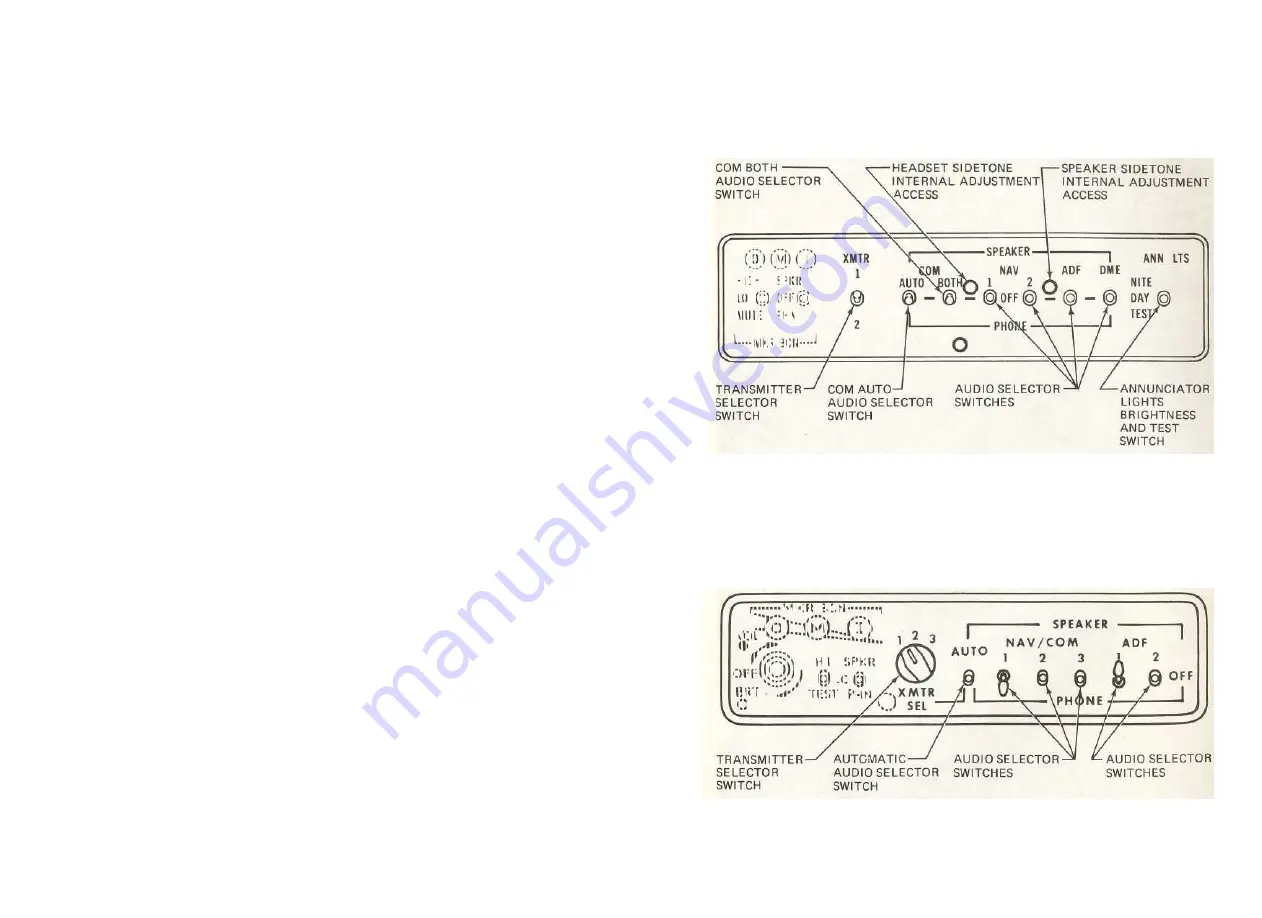
Two types of audio control panels (see figure 7-11) are available for
this airplane, depending upon how many transmitters are included. The
7-40
1 July 1979
CESSNA
SECTION 7
MODEL 172RG
AIRPLANE & SYSTEMS DESCRIPTIONS
USED WITH ONE OR TWO TRANSMITTERS
USED WITH THREE TRANSMITTERS
Figure 7-11. Audio Control Panel
1 July 1979
7-41


