background image

SECTION 1 

GENERAL 

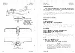
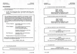
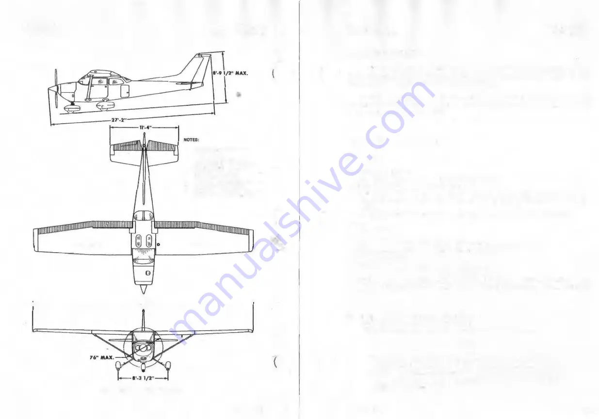
PIVOT  POINT 

CESSNA 

MODEL R172K 

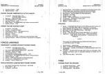
1.  Wing llj)On shown  with strobe 

lights insulled. 

2.  Maximum height  shown  with 

nose gear  depfoued, all tires ond 

note rtrut  properly  inflated, Ind 

flashing beacon inrtalled. 

3,  Wlleel base length Is 65". 

4.  Propeller i><ound  dur11nct is 10 3/4" 

5.  Wing ....  Is  174  -•  fNt. 

6.  Minimum  turning radius  (*pivot  Point 

to  outboard wing tip)  Is 27'•5  1/2". 

PIVOT  POINT 

t+-------------36'-0"-------------i 

Figure 1-1.  Three View 

1-2

1 July 1979 

CESSNA 

MODEL R172K 

SECTION 1 

GENERAL 

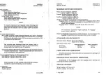
INTRODUCTION 

This handbook con ta.ins 9 sections, a.nd includes the material required 

to be furnished to the pilot by CAR Pa.rt 3. It also contains supplemental 

data supplied by Cessna Aircraft Company. 

Section  1  provides  basic  data  and information of general interest.  It 

also contains definitions or explanations of symbols, abbreviations, and 

terminology commonly used. 

DESCRIPTIVE  DATA 

ENGINE 

Number of Engines:  1. 

Engine Manufacturer:  Teledyne Continental. 

Engine Model Number:  1O-360-KB. 

Engine Type:  Normally-aspirated, direct-drive, air-cooled, horizontally­

opposed,  fuel-injected,  six-cylinder  engine with 360 cu.  in.  displace­

ment. 

Horsepower Ra.ting and  Engine  Speed:  195 rated BHP at 2600 RPM. 

PROPELLER 

Propeller Manufacturer:  McCauley Accessory Division. 

Propeller Model  Number:  2A34C203/90DCA-14. 

Number of Blades:  2. 

Propeller Diameter, Maxi.mum:  76 inches. 

Minimum:  74.5 inches. 

Propeller  Type:  Constant speed  a.nd  hydraulically actuated,  with a  low 

pitch setting of 12.0

° 

and a high pitch setting of 25.1 ° (30 inch station). 

FUEL 

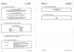
Approved Fuel Grades (and Colors): 

100LL Grade Aviation Fuel (Blue). 

100 (Formerly  100/130) Grade Aviation Fuel (Green). 

NOTE 

Isopropyl  alcohol  or ethylene glycol monomethyl  ether 

may be added to the fuel supply. Additive concentrations 

shall not exceed 1%  for isopropyl alcohol or  .15%  for 

ethylene glycol monomethyl ether. Refer to Section 8 for 

additional information. 

1 July 1979 

1-3 

Summary of Contents for R172K 1980

Page 1: ...ES 2 22 j 114 ICESSNA AIRCRAFT COMPANY I I 1980 MODEL R172K Serial No R1723306 Registration No VH VPM THIS HANDBOOK INCLUDES THE MATERIAL REQUIRED lO BE FURNISHED TO THE PILOT BY CAR PART 3 AND CONSTI...

Page 2: ...y most Cessna Dealers THE CESSNA WARRANTY which provides coverage for parts and labor isavailable at Cessna Dealers worldwide Specific benefits and provisions of warranty plus other important benefits...

Page 3: ...d to owners or u s Registered aircraft according to FAA records at the time o f revision issuance Revisions should be examined immediacely upon receip1and incorporaced in this handbook NOTE It is the...

Page 4: ...ECTION GENERAL 1 LIMITATIONS 2 EMERGENCY PROCEDURES 3 NORMAL PROCEDURES 4 PERFORMANCE 5 WEIGHT BALANCE EQUIPMENT LIST 6 AIRPLANE SYSTEMS DESCRIPTIONS 7 AIRPLANE HANDLING SERVICE MAINTENANCE 8 SUPPLEME...

Page 5: ...y Dimensions Baggage Space And Entry Dimensions Specific Loa dings Symbols Abbreviations And Terminology General Airspeed Terminology And Symbols Meteorological Terminology Engine Power Terminology SE...

Page 6: ...mmonly used DESCRIPTIVE DATA ENGINE Number of Engines 1 Engine Manufacturer Teledyne Continental Engine Model Number 1O 360 KB Engine Type Normally aspirated direct drive air cooled horizontally oppos...

Page 7: ...h a range of SAE 20W 50 is recom mended for improved starting in cold weather il Capacity 4 Sump 8 Quarts Total 9 Quarts 1 July 1979 CESSNA MODELR172K SECTION 1 GENERAL MAXIMUM CERTIFICATED WEIGHTS Ra...

Page 8: ...n in altitude in a given time METEOROLOGICAL TERMINOLOGY OAT Outside AirTemperature is thefree air statictemperature 1 6 1 July 1979 CESSNA MODELR172K Standard Tempera ture Pressure Altitude SECTION 1...

Page 9: ...f the airplane Center of Gravity Arm is the arm obtained by adding the airplane s individual moments and dividing the sum by the total weight Center of Gravity Limits are the extreme center ofgravity...

Page 10: ...the airplane its engine standard systems and standard equipment The limitations included in this section and in Section 9 have been approved by the Federal Aviation Administration Observance of these...

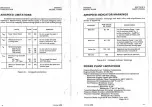
Page 11: ...ce are shown in figure 2 2 MARKING KIAS VALUE SIGNIFICANCE OR RANGE White Arc 38 85 Full Flap Operating Range Lower limit is maximum weight Vs in landing configuration Uppe limit is maximum speed perm...

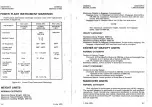
Page 12: ...e maximum combined weight ca pa city for baggage areas 1 and 2 is 200 lbs UTILITY CATEGORY Maximum Ra mp Weight 2208 lbs Maximum Takeoff Weight 2200 lbs Maximum Landing Weight 2200 lbs Maximum Weight...

Page 13: ...tors are 150 of the above and in all cases the structure meets or exceeds design loads UTILITY CATEGORY Flight Loa d Factors Ma xi mum Takeoff Weight 2200 lbs Flaps Up 4 4g 1 76g Flaps Down _ 3 0g 2 8...

Page 14: ...ng Handbook Baggage compartmentand rear seat must not be occupied Opposite rudder forward elevator neutralize controls Flight into known icing conditions prohibited This airplane is certified for the...

Page 15: ...00 RPM SL 16 GPH 4000 FT 14 GPH 8000 FT 12 GPH 12000 FT 10 GPH 8 A calibration card is provided to indicate the accuracy of the magnetic compass in 30 increments 9 On the flap control indicator 0 to 1...

Page 16: ...gine Power 3 4 Ditching 3 5 Fires 3 5 During Start On Ground 3 5 Engine Fire In Flight 3 6 Electrical Fire In Flight 3 6 Cabin Fire 3 7 Wing Fire 3 7 _ Icing 3 7 Inadvertent Icing Encounter 3 7 Static...

Page 17: ...lfunctions a re extremely re re if proper preflight inspections and maintenance a re practiced Enroute weather emergencies ca n be minim ized or eliminated by careful flight planning and good judgment...

Page 18: ...eed 65 KIAS 3 4 1 July 1979 I CESSNA MODELR172K SECTION3 EMERGENCY PROCEDURES 4 Selected Field FLY OVER notingterrain and obstructions then retract flaps upon rea hing a safe altitude and airspeed 5 A...

Page 19: ...d electrical power is necessary for continuance of light 6 Master Switch ON 3 6 1 July 1979 CESSNA MODELR172K SECTION 3 EMERGENCY PROCEDURES 7 Circuit Breakers CHECK for faulty circuit do not reset 8...

Page 20: ...oach 3 knots faster than normal 3 Altitude Cruise and approach 25 feet higher than normal LANDING WITH A FLAT MAIN TIRE 1 Approach NORMAL 2 Wing Flaps FULL DOWN 3 Touchdown GOOD TIRE FIRST hold airpla...

Page 21: ...ute a 180 gliding turn necessary to return to the runway The checklist procedures assume that adequate time exists to secure the fuel and ignition systems prior to touchdown After an engine failure in...

Page 22: ...gniting during an engine start causing a long flame Cromthetailpipe andpossibly ignitingthefuel puddle onthepavement In the eventthatthis occurs proceedin accordancewith theFire During Start On Ground...

Page 23: ...s prohibited in this airplane During instrument flight however icing conditions may be encountered inadvertently and therefore some corrective action will be required as shown in thechecklists Initiat...

Page 24: ...uel pump failure during takeoff immediately hold the auxilia ry fuel pump switch in the HIGH position until the airplane is well clear of obstacles Upon reaching a safe altitude and reducing power to...

Page 25: ...E illumination of the low voltage light and ammeter dis charge indications may occur during low RPM conditions with an electricalload on the system such a s during a low RPM ta xi Under these conditio...

Page 26: ...ing Trailing Edge Before Starting Engine Starting Engine Before Takeoff Takeoff Normal Takeoff Short Field Takeoff Enroute Climb Normal Climb Maximum Performance Climb Cruise Descent Before Landing La...

Page 27: ...tems can be found in Section 9 SPEEDS FOR NORMAL OPERATION Unless otherwise noted the following speeds are based on a maximum weight of 2550 pounds and may be used for any lesser weight However to ach...

Page 28: ...VE and STOW 3 Ignition Switch OFF 4 Avionics Power Switch OFF 5 Master Switch ON I WARNING When turning on the master switch using an external power source or pulling the propeller through by hand tre...

Page 29: ...ump quick drain valve to check for water sediment and proper fuel grade 3 Fuel Quantity CHECK VISUALLY for desired level 4 Fuel Filler Cap SECURE z LEFT WING leading Edge 1 Pitot Tube Cover REMOVE and...

Page 30: ...OSE WHEEL at 55 KIAS 5 Climb Speed 75 85 KIAS SHORT FIELD TAKEOFF 1 Wing Flaps 10 4 8 1 July 1979 I t CESSNA MODELR172K SECTION 4 NORMAL PROCEDURES 2 Brakes APPLY 3 Power FULL THROTTLE and 2600 RPM 4...

Page 31: ...er Trim ADJUST 5 Power REDUCE TO IDLE as obstacle is cleared 6 Touchdown MAIN WHEELS FIRST 7 Brakes APPLY HEAVILY 8 Wing Flaps RETRACT for maximum brake effectiveness BALKED LANDING 1 Power FULL THROT...

Page 32: ...turned on accidentally while the engine is stopped with the throttle open a nd the mixture rich solid fuel will collect temporarily in the cylinder intake ports the quantity depending on the amountof...

Page 33: ...an ca use serious engine damage NOTE Additional details concerning cold weather starting a nd operation may be found under Cold Weather Oper ation paragraphs in this section TAXIING When taxiing it is...

Page 34: ...as required in other flight conditions to maintain a fixed throttle setting 4 16 1 July 1979 CESSNA MODELR172K WING FLAP SETTINGS SECTION 4 NORMAL PROCEDURES Normal takeoffs are accomplished with win...

Page 35: ...e Table 4 18 1 July 1979 CESSNA MODELR172K SECTION 4 NORMAL PROCEDURES green a re range for a givenpercent power thatwill providesmoothengine operation The cowl flap should be opened if necessary to m...

Page 36: ...orientation 4 20 1 July 1979 CESSNA MODELR172K SECTION4 NORMAL PROCEDURES The nonna l entry is made from a power off stall As the stall is approached the elevator control should be smoothly pulled to...

Page 37: ...nimum na p setting required for the field length If flap settings greater than 20 a re used in sideslips with full rudder deflection some elevator oscillation may be felt 4 22 1 July 1979 CESSNA MODEL...

Page 38: ...pplic a tion of the following suggested procedures and thereby tend to build public support for aviation 1 Pilots operating aircraft under VFR over outdoor assemblies of persons recreational and park...

Page 39: ...planning of flights in detail and with reasonable accuracy The data in the chartshas been computedfrom actual flight tests with the airplane and engine in good condition and using averagepiloting tec...

Page 40: ...wind enroute have been given for this sample problem However the power setting selection for cruise must be deter mined based on several considerations These include the cruise perfor mance characteri...

Page 41: ...e the flight is underway ground speed checks will provide a more ccurate basis for estimating the time enroute and the corresponding fuel 6 1 July 1979 l CESSNA MODEL R172K required to complete the tr...

Page 42: ...D WINDOWS CLOSED FLAPS UP NORMAL KIAS 50 60 70 80 90 100 110 120 130 140 150 160 ALTERNATE KIAS 43 57 69 79 90 100 109 119 128 137 147 156 FLAPS 10 NORMAL KIAS 40 50 60 70 80 90 100 110 ALTERNATE KIAS...

Page 43: ...on Chart 5 10 1 July 1979 CESSNA MODEL R172K SECTION 5 PERFORMANCE STALL SPEEDS CONDITIONS Power Off NOTES 1 Maximum altitude loss during a stall recovery may be as much as 160 feet 2 KIAS values are...

Page 44: ...NDITIONS AND NOTES TAKEOFF o0 c 10 c 2o c 3D C WEIGHT SPEED PRESS KIAS ALT LBS TOTAL TOTAL TOTAL TOTAL LIFT AT FT GRND TO CLEAR GRND TO CLEAR GANO TO CLEAR GANO TO CLEAR OFF 50 FT ROLL 50 FT OBS ROLL...

Page 45: ...Flaps Up 2600 RPM Full Throttle Mixrure Set at Placard Fuel Flow Cowl Flap Open Standard Temperature NOTES MIXTURE SETTING 1 Add 1 4 gallons of fuel for engine start taxi and takeoff allowance 2 Incre...

Page 46: ..._ 9oc RPM MP KTAS GPH BHP 2600 24 23 78 122 11 1 22 73 118 10 3 21 68 114 9 6 2500 25 24 80 122 11 2 23 75 119 10 6 22 70 116 9 9 2400 25 79 122 11 2 24 74 119 10 5 23 70 116 9 9 22 65 112 9 2 2300 25...

Page 47: ...101 7 4 49 97 7 1 47 95 6 9 45 91 6 6 43 89 6 4 Figure 5 7 Cruise Performance Sheet 2 of 6 5 18 1 July 1979 CESSNA MODEL R172K SECTION 5 PERFORMANCE CRUISE PERFORMANCE PRESSURE ALTITUDE 6000 FEET COND...

Page 48: ...10 8 2 55 109 7 9 53 105 7 7 51 103 7 4 49 99 7 1 47 97 6 9 45 93 6 6 43 91 6 4 Figure 5 7 Cruise Performance Sheet 4 of 6 5 20 1 July 1979 CESSNA MODEL R172K SECTION 5 PERFORMANCE CRUISE PERFORMANCE...

Page 49: ...0 103 7 2 47 98 6 9 46 96 6 7 43 90 6 4 41 88 6 2 53 106 7 6 51 104 7 4 48 100 7 1 47 98 6 8 44 93 6 5 43 90 6 3 49 101 7 1 47 99 6 9 45 94 6 6 44 92 6 4 Figure 5 7 Cruise Performance Sheet 6 of 6 5 2...

Page 50: ...t 1 t t 1 1 HH l l l I I 6000 A _ _ _ do 122 112 oo 1 KTAS KTAS 1 KTAS KTAS RANGE NAUTICAL MlLES Figure 5 8 Range Profile Sheet 2 of 2 1 July 1979 I I CESSNA MODELR172K SECTION 5 PERFORMANCE CONDITIO...

Page 51: ...up to 10 knots increase distances by 10 for each 2 knots 3 For operation on a dry grass runway Increase distances by 40 of the ground roll figure SPEED o 0 c 10 c 20 c 30 C PRESS Q C if WEIGHT AT ALT...

Page 52: ...EROPLANE WEIGHT AND CENTRE OF GRAVITY DATA ITEM WEIGHT ARM INDEX UNIT CABIN Kg mm aft Kg mm CONFIGURATION of datum EMPTY 804 4 953 766709 FOUR SEATS TOTAL STANDARD CABIN CONFIGURATION STC SA1437CE ISH...

Page 53: ...EC 60 Fire Ext Portable 0 Speakers 1 G slope ARC R4438 Cabin Heater Muff 1 Vacuum Pumps 1 Headsets 1 Heated Pilots 1 HF Com 0 Alternate Static 1 Nav Com ARC RT385A Electric Trim 0 Audio CESSNA 300 Whe...

Page 54: ...ug to drain all oil d Move sliding sea ts to the most forward position e Raise flaps to the fully retracted position r Place all control surfaces in neutral position 2 Leveling a Place scales under ea...

Page 55: ...at upper door sill or leveling screws on left side of tailcone Symbol Net Weight L R N w I X I IN Moment 1000 Weight Lbs X C G Arm In Lbs ln 17 21 5 0 4 46 0 45 0 Figure 6 1 Sample Airplane Weighing...

Page 56: ...ee limitation Additional moment calculations based on the actual weight and C G arm fuselage station of the item being loaded mustbemade if the position of the load is di fferentfrom that shown on the...

Page 57: ...Use the data pertaining to your 2 8 airplane as it is presently equipped Includes unusable Dy fuel and full oil 1592 56 7 Usable Fuel At 6 Lbs Gal fb4 Standard Tanks 49 Gal Maximum 294 14 1 Long Rang...

Page 58: ...I I I I II I I I l 1 1111 1111111111 111111111 0 0 5 10 16 20 25 30 LOAD MOMENT 1000 POUND INCHESI NOTE Line representing adjustable seats shows the pilot or passenger center of gravity on adjustable...

Page 59: ...plant Accessories under which it is listed Suffix letters identify the equipment as a required item a standard item or an optional item Suffix letters are as follows R required items of equipment for...

Page 60: ...TI LL ATI ON A P C I NSTRU ENT FLOC10 0QOQOQS T MOUNTE D LI GHTS CQUR TFSY S ET OF TWO F TECTCRS NAVI GA TI ON LI GHT SET OF TWO LI GHT INSTA LL ATI ON OMNlFL ASH BEACON A ACON LI GH T IN FI N TIP FLA...

Page 61: ...HT ODOR HINGED NET CHANGE WINDOWS OVERHEAD CABIN TOP NET INCREASE VENTILATION SYSTEM REAR SEAT CIIP HOLIJER RF TRAC TABLE I SET OF TWCI HEAORE T FRONT ISET OF TkOI HFAOREST REAR SET OF TWO SUN VlSOR S...

Page 62: ...lTO RADIA L CENTER ING IN DIC ATOR ARC LS EXCH ANGE OR VOR ILS USED WITH H 7 A ON LY WT IS NF T CHANGE ARC ILS IN DICATOR ADDED vnR ILS I NDICATOR DELETED Hll A 1 I PANTRONICS PTl A HF TRANSCEIVER 2ND...

Page 63: ...SPLITTER 3 0111 3 0 2 1 0 ID COM ANTENNA RH VHF 3960113 2 0 4 62 4 m co _ _ s o ITEM NO EQUIPMENT LIST DESCRIPTION REF DRAWING WT LBS ARM INS ol I t Ol t_ i j C l t H43 A AV I nN CS n PTI ON O NA V 0...

Page 64: ...FUSELAGE MOD I FI CATIONS EQUIPMENT LIST DESCRIPTION J 11 t COW L DECK BR AC E STOW ED J l5 A INTERCONNEC T SYSTEM STOWED INSTAL LED ARM SHCW N FLOATPLANF KIT W I TH CORROSION PROOFING BUT NO PROP CH...

Page 65: ...7 12 Shoulder Harnesses 7 14 Integrated Seat Belt Shoulder Harnesses With Inertia Reels 7 14 Entrance Doors And Cabin Windows 7 15 Control Locks 7 16 Engine 7 16 Engine Controls 7 16 Engine Instrumen...

Page 66: ...tached a bulkhead and forgings for main landing gear attachment at the base of the rear door pbsts and a bulkhead with attach fittings at the ba se of theforward doorposts for the lowerattachmentofthe...

Page 67: ...4 RUDDER AND RUDDER TRIM CONTROL SYSTEMS Figure 7 1 Flight Control and Trim Systems Sheet 1 of 2 1 July 1979 l I I CESSNA MODELR172K SECTION7 AIRPLANE SYSTEMS DESCRIPTIONS ELEVATOR CONTROL SYSTEM ATO...

Page 68: ...sure Fuel Flow 32 Static Pressure Alternate Indicator Source Valve ti 8 Flight Instrument Group 33 Instrument and Radio Dial CQ 9 Airplane Registration Number Light Dimming Rheostats I 10 Tachometer 3...

Page 69: ...gyros respectively The remainder of the filght instruments are located a round the basic T Engine instruments fuel quantity indicators an ammeter and a low voltage warning light a re near the left ed...

Page 70: ...baggage and is attached by tying the straps to tie down rings provided in the airplane When loading the airplane children should not be placed or permitted in the baggage compartment unless a child s...

Page 71: ...he child s sea t To a djust the headrest apply enough pressure to it to ra ise or lower it to the desired level The headrest may be removed at anytime by raising it until it disengages from the top of...

Page 72: ...r ness comfort and safe retention of the seat occupants This location requires that the shoulder harnesses cross near the top so that the right hand inertia reel serves the pilot 1 July 1979 CESSNA MO...

Page 73: ...to decrease it 7 16 1 July 1979 CESSNA MODELR172K SECTION7 AIRPLANE SYSTEMS DESCRIPTIONS The mixture control mounted above the right corner of the control pedesta l is a red knob with ralsed points a...

Page 74: ...use lubricating oil to bypass the filter in the event the filter becomes plug Sed or the oil temperature is extremely cold 7 18 1 July 1979 CESSNA MODEL t1178K BECTION7 AIRPLANE SYSTEMS DESCRIPTIONS A...

Page 75: ...This is omplished by movingthe lever to the left to clear a detent thenmoving i lever up to the OPEN position Anytime the lever is repositioned it 0 1 July 1979 CESSNA MODELR172K SECTION7 AIRPLANE SYS...

Page 76: ...ndard tank approximately 1 gallon remains in along range tank as unusable fuel The indicators cannot be relied upon for accurate readings during skids slips or unusual flight attitudes If both indicat...

Page 77: ...low to maintain flight in the eventof an engine driven fuel pump failure As the throttle is moved toward the closed position during letdown landing or taxiing fuel flow provided by the pump is automat...

Page 78: ...ttention If during taxi or landing roll braking action decreases let up on the peda ls a nd then re apply the brakes with heavy pressure If the brakes become spongy or peda l tra vel increases pumping...

Page 79: ...approximately two minutes before placing the 11witch in the ON position again If the circuit breaker opens again do notreset it The avionicspower switch should beplaced in the off position prior to t...

Page 80: ...hrough clouds or overcast the flashing lightreflectedfromwater droplets orparticles inthe atmosphere particularly atnight ca n produce vertigo andlossoforienta tion INTERIOR LIGHTING Instrumentpanel a...

Page 81: ...et the breaker and turn the switch on again Ifthe breaker opens a gain do not reset it CABIN HEATING VENTILATING AND DEFROSTING SYSTEM The temperature and volume of airflow into the cabin can be regul...

Page 82: ...1979 CESSNA MODELR172K SECTION 7 AIRPLANE SYSTEMS DESCRIPTIONS manner similar to the operation of a flight computer To operate the indicator first rotate the ring until pressure altitude is aligned w...

Page 83: ...ional indicators The desired suction range is 4 5 to 5 4 inches of mercury A suction reading below this range may indicate a system malfunction or improper adjust ment and in this case the indicators...

Page 84: ...eNAV COM is also selected and is used for ALL speaker audio In the event the audio amplifier in use fails as evidenced by loss of all speaker audio selecting an alternate transmitter will reestablish...

Page 85: ...tch in the up SPEAKER position so that the number two communications receiver audio will be heard in addition to the number one communications receiver audio This feature can also be used when listeni...

Page 86: ...s a re also available these feature a single unit microphone headset combina tion which permits the pilot to conduct radio communications without interrupting other control operations to handle a hand...

Page 87: ...d take advanta ge of his knowledge and experience He knows your airplane and how to maintain it He will remind you when lubrications and oil changes are necessary f and about other seasonal and period...

Page 88: ...Airworthiness Certificate FAA Form 8100 2 2 Aircraft Registration Certificate FAA Form 8050 3 3 Aircraft Radio Station License iftransmitterinstalled FCCForm 556 B To be carried in the airplane at all...

Page 89: ...he first 6 months of ownership atnochargetoyou If you take delivery from your Dealer the initial inspectionwillhave been performed before delivery of the airplane to you If you pick up your airplane a...

Page 90: ...buckling the skin To assist in raising and holding the nose wheel offthe ground weight down the tail by placing sand bags or suitable weights on eachside ofthe 8 8 1 July 1979 I I CESSNA MODELR172K SE...

Page 91: ...ended flight fill to 8 quarts These quantities refer to oil dipstick level readings Duringoil andoil filter changes one additionalquartis required when the filter is changed 8 10 1 July 1979 CESSNA MO...

Page 92: ...alcohol orEGME compound into the fuel provides two distinct effects 1 it absorbs thedissolvedwaterfrom the gasoline and 2 alcohol has a freezing temperature depressant effect Alcohol if used is to be...

Page 93: ...to craze Follow by carefully washing with a mild detergent and plenty of water Rinse thoroughly then dry with a clean moist chamois Do not rub the plastic with a dry cloth slnce thls builds up an ele...

Page 94: ...ue or rags Don t pat the spot press the blottingmaterialfirmly andholditfor several seconds Continue blotting until no more liquid is taken up Scrape off sticky materials with a dull knife then spot c...

Page 95: ...al Encoding Altimeter Type EA 401A 1 July 1979 48 pages I 4 pages 4 pages 4 pages 2 pages 2 pages 4 pages 4 pages 8 pages 4 pages 4 pages 6 pages 6 pages 8 pages 6 pages 6 pages 6 pages 4 pages 6 page...

Page 96: ...n side windows The circulation fan andmotorincludes anelectricmotor equippedwith a n output shaft on each end attached to squirrel cage type blowers within blower housings which provide airflow throug...

Page 97: ...Cabin Air Control Knob PULL OUT 3 Wing Root Ventilators OPEN 4 CIRCULATION FAN Control Knob HI BEFORE TAKEOFF 1 Cabin Window s CLOSED AND LOCKED OPERATION IN FLIGHT The inflight operation of the circu...

Page 98: ...stallation is installed in accordancewith STC sSE1436CE for the engine and SA1437CE for the airplane use ofengine andoptional Model P 1000 tachometer The information contained herein supplementsorsupe...

Page 99: ...C SA1437CEallows use of the modified engine in theCessna R172K airplanes If heairplane Isequipped with the Horizon Instruments Inc P 1000 Digital Tachometer refer to Appendix 1of thisAFMS SECTION 2 LI...

Page 100: ...uments Inc Model P 1000Tachometerin the Cessna R172K airplanes SECTION 2 LIMITATIONS Engine Model Number I0 360 KC SE1436CE or IO 360 KBC SE1436CE Engine Operating Limits for takeoffand continuous ope...

Page 101: ...ems D E andF FAA D te Qicm 17 1978 Fe tsialA Jney28 1932 Fe tsia1a 1ney28 1001 Fe tsia1C lt gJSt4 DJ Threesmall LED magneto system alertind tcatorlights arelocated withinthe Status area on the upper l...

Page 102: ...sing and releasing the left button K causes theTachorneter to maskor un mask the left internal tachometer FM lie Qicm17 1978 Fe AsmA Jnay28 1002 Fe ismB Jnay28 1001 FeJisme J1tg s4 am l Appendix 1 Pag...

Page 103: ...has slowed This is indicated as anegative number on thedisplay numberis preceded by aleading hyphen or minus sign LED Indicators aredim able exceptthe restricted or red ightindicator toreduce pilot an...

Page 104: ...al and configuration information see Figure5 Horizon Instruments Inc 556 S StateCollegeBlvd Fullerton CA 92631 Model P 1000 Digital Tachometer H W PIN PI00 058 619 00 Software PIN P132001 VERS 1 06 6...

Page 105: ...yd T August 22 I967 February 26 I968 Mor 8 1976 Mor 14 1983 Feb 6 1987 June JS 1990 Feb 25 2000 Sec Page Softhls STC Slr onn Manager Airframe Branch Los Angeles Aircraft Certification Office TIii tlnU...

Page 106: ...al Airplane Flight Manual No 171 dated August 17 1988 or later FAA Approved Revisions is required Forairplanes with transfer pumps and with FAA Approved Airplane Flighl Manuals FAA Approved Flint Aero...

Page 107: ...720 72L 72r t 2G 1 2H 1721 172K 172L 172M 72N 172 1720 172R ns F172F F172G F172H F172K F172L F172M F172N FR172E FR172F FR1 f2G FR172H FR172J FR172K 175 175A 175B 175C R172K 172RG R172E Rems Av1e11on S...

Page 108: ...FICATIONS WITH INTERNAL AUXILIARY TANKS SPEED CRUISE CLIMB TAKEOFF LANDING No Chanlie Max Cruise Power Standaro Day Condohons No Cnange _ Wolh fuel allowance for eng ne sIer1 tax takeoff chmb and 45 m...

Page 109: ...and 1 3 below Table 1 2 FUEL CAPACITY U S GALLONS I CESSNA MODELS 0 0 0 i LL a r i N a z 5 w 0 0 _ 1 Tolal Capacity _ 8 66 66 63 _ 66 _ 66 76 Total Usable 76 73 63 61 59 62 60 65 Total Capacity Ea _h...

Page 110: ...y lank filler 12 U S gal 100 130 11In grade Av Gasoline Aux fuel switch must be off before filling 10 7 For Models 172N SIN 17261578 17269310 17274009 172P 1720 172R 172S R172K SIN R1722725 an l on 17...

Page 111: ...ed Calculate the cruise Miles per Gallon by dIv1ding the Airspeed by the fuel consumption m gallons per mile Miles Hr Gal I Hr Miles I Gal Then multiply the miles per gallon by 23 gallons the usable f...

Page 112: ...he Cessna main fuel tanks two auxihary fuel transfer ranks are installed The capacity is 12 0 U S gallons each 1an1 11 5 usable U S gallons each1 These tanks transfer to their respective main wing lan...

Page 113: ...s the authority to amend or add to any existing Pilot Owners Handbook This document serves as an example of a Model P 1000 Electronic Digital Engine Tachometer Flight Manual Supplement which must be a...

Page 114: ...ARC4 LOWEST ARC a RPM 2 800 COLOR RPM COLOR RPM COLOR RPM COLOR RPM COLOR L __ RED 2Z22 YEL 2592 GRN 6 2600 2200 The face of the P 1000 tachometer is placarded with the Engine RPM Operating Range info...

Page 115: ...000 Electronic Digital Engine Tachometer Horizon Instruments Inc 600 S Jefferson st Unit C P1acentla CA 92870 Ph 714 52 1919 Fx 7111 524 5937 the non fractional portion 0000 of the current accumulated...

Page 116: ...light and the display of the amount of RPM that the engine has slowed This Is indicated as a negative number on the display number is preceded by a leading hyphen or minus sign LED indicators are dim...

Page 117: ...Office DATE OF APPROVAL _ Zm ISSUED February 4 2000 1 of 8 PULL OPERATED CABLE VALVE SYSTEM DESCRIPTION Standby Vacuum System AFM SUPPLEMENT A Precise Flight Standby Vacuum System may be installed to...

Page 118: ...ice system when operating with a failed primary vacuum system 4 Above I0 000 ft pressure altitude engine power settings may have to be significantly reduced to provide adequate vacuum power for proper...

Page 119: ...aft with a Fixed Pitch Propeller PRESS SVSVACUUM ALT FT RPM IN HG MIN 2000 4000 6000 8000 10 000 ISSUED February 4 2000 5 of 8 I I PULL OPERATED CABLE VALVE Standby Vacuum System AFM SUPPLEMENT II OPE...

Page 120: ...AILURE OF THE VACUUM SYSTEM STILL CONSTITUTES AN EMERGENCY SITUATION REGARDLESS OF THE INSTALLATION OF THE SVS IT MAY NOT BE POSSIBLE TO MAINTAIN A SAFE ALTITUDE AND MAKE USE OF THE SVS IN SUCH A SITU...

Page 121: ...1RF F7392 propeller with C 4582 P spinner or P HC C3YF 1RF F7392 propeller with A 2295 l P spinner in accordance with STC The infonnation contained herein supplements or supersedes the basic manual o...

Page 122: ...nstruments No change SECTION 3 EMERGENCY PROCEDURES Power offdescent rate with the Hartzell three blade is greater than the McCauley two blade configuration The higher descent rate represents a 13 red...

Reviews: