CET Electric Technology
12
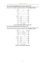
2.6.9 1-Phase 2-Wire, Ull (1P2W-Ull) Direct Connection with 1CT
Please consult the Serial Number Label to ensure that the rated system line voltage is less than or equal
to the meter’s rated line voltage input specification. Set the Wiring Mode to 1P2W, L-L.
Figure 2-20 1P2W Ull Direct Connection with 1CT
2.7 Communications Wiring
2.7.1 Ethernet Port (10/100BaseT)
The following table illustrates the pin definition for the RJ45 Ethernet connector.
RJ45 Connector
Pin
Meaning
1
Transmit Data+
2
Transmit Data-
3
Receive Data+
4,5,7,8
NC
6
Receive Data-
Table 2-1 RJ45 Connector Pin Description for 10/100BaseT Applications
2.7.2 RS485 Port
The following figure illustrates the RS485 communications connections on the PMC-53A-E:
Figure 2-21 Communications Connections
The PMC-53A-E provides one standard RS485 port. Up to 32 devices can be connected on a RS485 bus.
The overall length of the RS485 cable connecting all devices should not exceed 1200m.
If the master station does not have a RS485 communications port, a RS232/RS485 or USB/RS485
converter with optically isolated output and surge protection should be used.
2.8 Digital Input Wiring
The following figure illustrates the Digital Input connections on the PMC-53A-E:
Figure 2-22 DI Connections


