CET Electric Technology
39
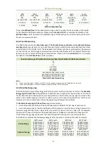
scheme is equivalent to having an implicit Logical OR operation for the control of a Digital Output and
may be useful in providing a generic alarm output signal. However, the sharing of a Digital Output is not
recommended if the user intends to generate a control signal in response to a specific setpoint condition.
4.1.3 Energy Pulse Outputs
The PMC-53A-E comes standard with one Front Panel LED Pulse Output for energy pulsing and can be
equipped with two optional Solid State Digital Outputs for kWh and kvarh pulsing, replacing the default
Digital Outputs. Energy Pulse Outputs are typically used for accuracy testing. Energy Pulsing via the
Front Panel LED can be enabled from the Front Panel through the LED EN Pulse setup parameter. The
pulse constant can be configured as 1000/3200/6400 pulses per kWh/kvarh through the EN Pulse CNST
setup parameter.
4.1.4 Analog Input
The PMC-53A-E comes optionally with an Analog Input which can be programmed as 0mA to 20mA or
4mA to 20mA input. There are 3 setup parameters:
Type:
Select between 0-20mA or 4-20mA input.
AI Zero: This value corresponds to the minimum Analog Input of 4 mA (for 4-20mA input) and
has a range of -999,999 to +999,999.
AI Full: This value corresponds to the maximum Analog Input of 20 mA and has a range of -
999,999 to +999,999.
For example, to measure the oil temperature of a transformer, connect the outputs of the temperature
sensor to the AI terminals of the PMC-53A-E. The temperature sensor outputs 4mA when the
temperature is -25°C and 20mA when the temperature is 100°C. As such, the Type parameter should
be programmed as 4-20mA. The AI FULL parameter should be programmed with the value 100, and the
AI ZERO parameter should be programmed with the value -25. Therefore, when the output of the
sensor is 20mA, the reading will be 100.00°C. When the output is 4mA, the reading will be -25.00°C.
When the output is 12mA, the reading will be (100°C - (-25°C)) x (12mA-4mA) / (20mA-4mA) + (-25°C)
= 37.50°C.
4.2 Power and Energy
4.2.1 Basic Measurements
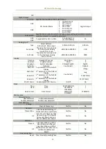
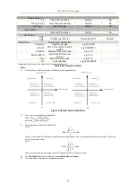
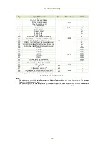
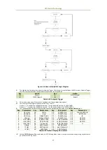
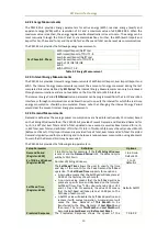
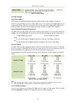
The PMC-53A-E provides the following basic measurements which are available through the Front Panel
or communications.
Parameter
Phase A
Phase B
Phase C
Total
Average
Uln
●
●
●
-
●
Ull
●
●
●
-
●
Current
●
●
●
-
●
Neutral Current
-
-
-
In (Calculated)
I4 (Optional)
Residual Current
-
-
-
Ir
-
kW
●
●
●
●
-
kvar
●
●
●
●
-
kVA
●
●
●
●
-
PF
●
●
●
●
-
dPF
●
●
●
●
-
Frequency
●
U Fundamental
●
●
●
I Fundamental
●
●
●
P Fundamental
●
●
●
●
Table 4-2 Basic Measurements
Notes:
1)
When the Wiring Mode is 3P3W, the per-phase Uln, kW, kvar, kVA and Power Factor are reserved.
2)
The Frequency detection priority is: U1 (U12) > U2 (U23) > U3 (U31). For example, if U1=0, the U2 signal would be used for
Frequency detection instead. If both U1 and U2 are 0, the U3 signal would be used for Frequency detection.

