CET Electric Technology
53
Please note that the error detection above is based on the following assumptions:
The Voltage and Current Phase Sequences are consistent
kW is kW Import, which means the kW is over 0
3P4W wiring mode supports all detections
3P3W wiring mode does not support the detection of Voltage Phase Loss, kW Direction per phase
and CT Polarity
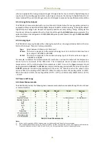
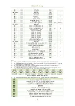
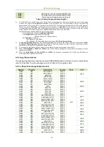
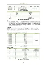
The Diagnostic register (0101) illustrated below indicates the status of the various wiring error detection
with a bit value of 1 meaning active and 0 meaning inactive:
Bit
Event
B00
Summary Bit (Set if any other bit is set)
B01
Frequency is out of range (45 to 65Hz) (3P4W or 3P3W)
B02
Voltage Phase Loss (3P4W only)
B03
Current Phase Loss
(Register 6004) (3P4W or 3P3W)
B04-B05
Reserved
B06
Voltage Phase Reversal (3P4W only)
B07
Current Phase Reversal (3P4W or 3P3W)
B08
Negative kW Total may be abnormal (3P4W or 3P3W)
B09
Negative kWa may be abnormal (3P4W only)
B10
Negative kWb may be abnormal (3P4W only)
B11
Negative kWc may be abnormal (3P4W only)
B12
CTa polarity may be reversed (3P4W only)
B13
CTb polarity may be reversed (3P4W only)
B14
CTc polarity may be reversed (3P4W only)
B15
Disconnection of Residual Current Input
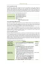
Table 4-19 Wiring Diagnostic Register
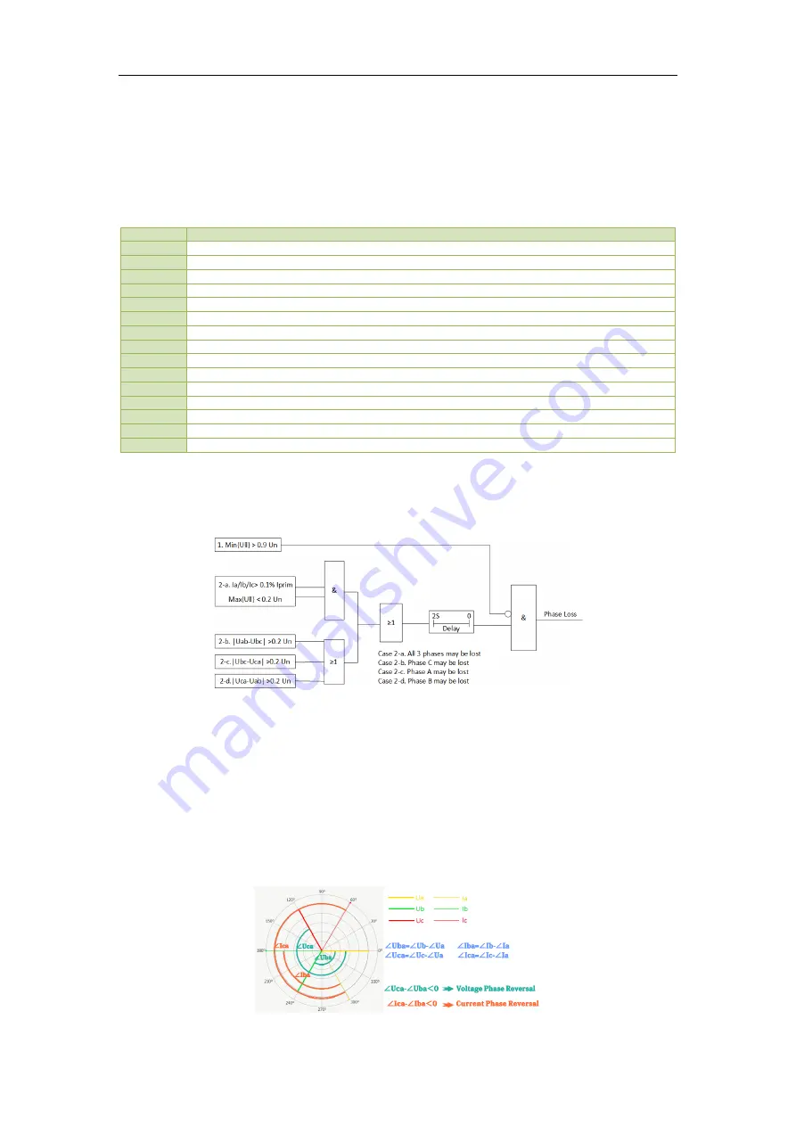
4.8.1 Voltage Phase Loss
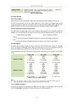
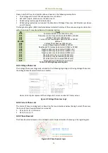
The Voltage Phase Loss diagnostic is based on the following logic diagram (During Voltage Phase Loss,
the Voltage Phase Reversal detection is invalid).
where Un and Iprim represents the Voltage and Current nominal in Primary values
Figure 4-9 Voltage Phase Loss Logic
4.8.2 Current Phase Loss
The Current Phase Loss diagnostic is based on the two detections below (During Current Phase Loss,
the Current Phase Reversal Detection is invalid):
1.
Max {Ia, Ib, Ic} ≥ 0.1% Iprim
2.
Min {Ia, Ib, Ic} = 0
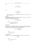
4.8.3 Phase Reversal
The Phase Reversal is based on the Voltage/Current Angles detection. Following is the logic diagram.
Figure 4-10 Phase Reversal Logic

