CET Electric Technology
16
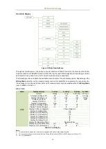
3.1.2 Data Display
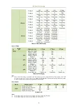
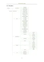
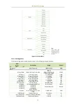
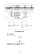
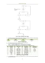
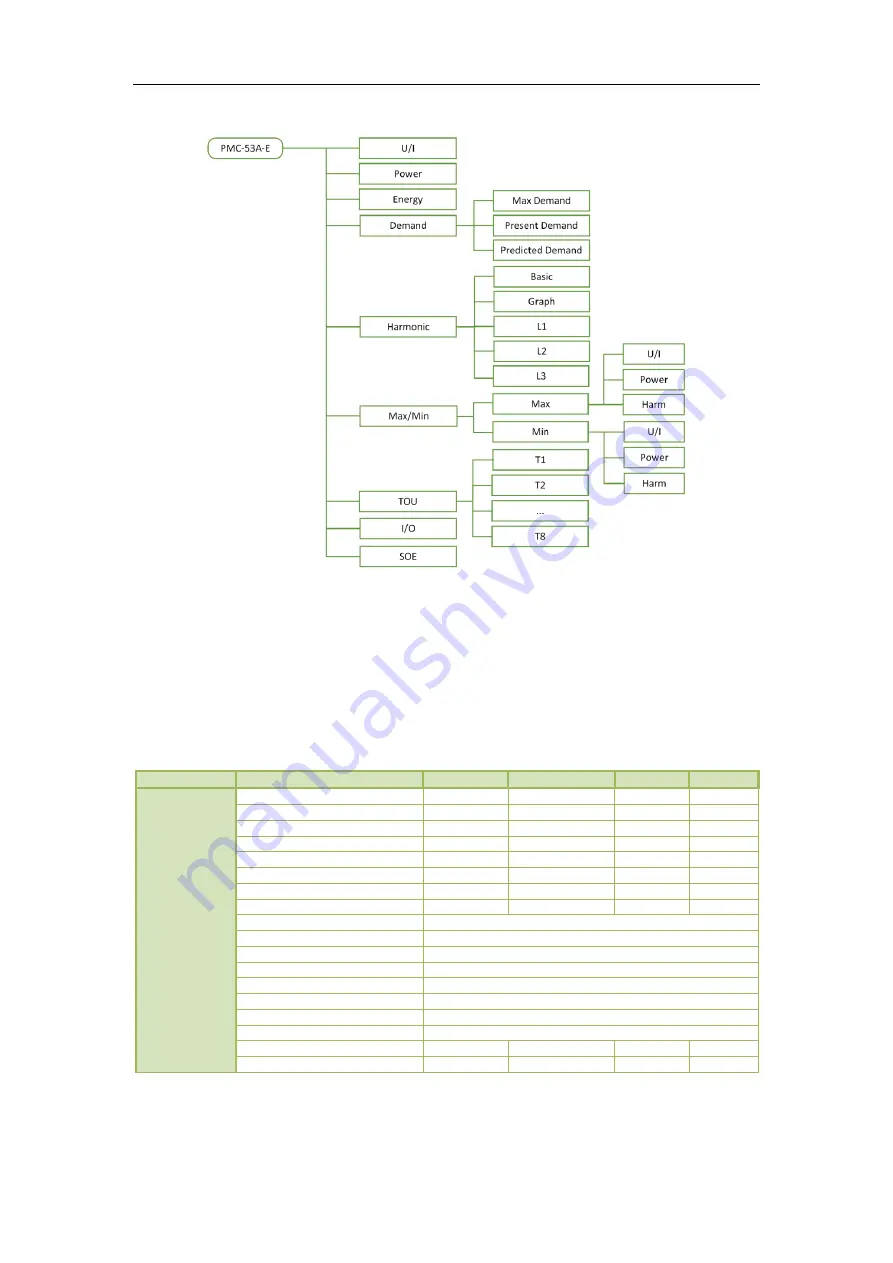
Figure 3-2 Data Display Menu
Throughout this document, the phase-to-neutral notations of A/B/C and L1/L2/L3 as well as the phase-
to-phase notations of AB/BC/CA and L12/L23/L31 may be used interchangeably for specifying a certain
parameter to be a phase-to-neutral or phase-to-phase value, respectively.
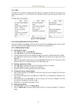
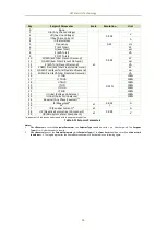
The following sections illustrate the available measurements for each display option. Depending on the
Wiring Mode selected, certain measurements may not be available. For example, the per-phase Uln,
Uln Average, I4, per-phase kW, kvar, kVA and PF measurements are not available when the Wiring Mode
is set to 3P3W or 1P2W L-L.
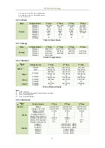
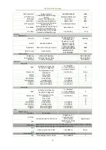
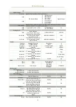
3.1.2.1 U/I
Menu
Display Screens
1
st
Row
2
nd
Row
3
rd
Row
4
th
Row
<U/I>
Default
Ull avg
I avg
kW Total
PF Total
Display 1 (Voltage L-N)
U1
U2
U3
Uln avg
Display 2 (Voltage L-L)
U12
U23
U31
Ull avg
Display 3 (Current)
I1
I2
I3
I avg
Display 4 (In/I4/Ir)
In
I4
1
Ir
2
Display 5 (Frequency)
Freq.
Display 6 (Voltage Angle)
U1
U2
U3
Display 7 (Current Angle)
I1
I2
I3
Display 8 (Phasor Diagram)
Phasor Diagram
Display 9 (U Waveform)
U1
Display 10 (U Waveform)
U2
Display 11 (U Waveform)
U3
Display 12 (I Waveform)
I1
Display 13 (I Waveform)
I2
Display 14 (I Waveform)
I3
Display 15 (Operating Time)
Operating Time
Display 16 (U Fundamental)
U1
3
U2
3
U3
3
Display 17 (I Fundamental)
I1
3
I2
3
I3
3
Table 3-2 U/I Display
Notes:
1)
This parameter only appears if the meter is equipped with the corresponding I4 option.
2)
This screen only shows a valid value when the Wiring Mode is set to 3P3W or 3P4W, otherwise, it shows “0”.
3)
For U/I Fundamental:

