CET Electric Technology
38
Chapter 4 Applications
4.1 Inputs and Outputs
4.1.1 Digital Inputs
The PMC-53A-E comes standard with four self-excited Digital Inputs that are internally wetted at 24 VDC
with a sampling frequency of 1000Hz and programmable debounce. The PMC-53A-E provides the
following programmable functions for its digital inputs:
1)
Digital Input
The digital inputs are typically used for status monitoring which can help
prevent equipment damage, improve maintenance, and track security
breaches. The real-time statuses of the Digital Inputs are available on the
Front Panel LCD Display as well as through communications. Changes in
Digital Input status are stored as events in the SOE Log in 1 ms resolution.
2)
Pulse Counting
Pulse counter is supported with programmable Pulse Weight and
facilitates WAGES (Water, Air, Gas, Electricity and Steam) information
collection.
3)
Tariff Switching
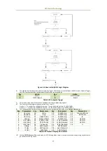
Up to 3 Digital Inputs may be used to select to which of the 8 Tariffs the
energy consumption should be accumulated. The 3 Digital Inputs (DI1, DI2
and DI3) represent 3 binary digits where Tariff 1=000, Tariff 2=001, …,
Tariff 8=111 where DI1 represents the least significant digit and DI3
represents the most significant digit. The DI1 Function setup register
must first be programmed as a Tariff Switch before configuring DI2 with
the same function. In other words, if DI1 is configured as a Digital Input
or Energy Pulse Counter and DI2 is configured as a Tariff Switch, the TOU
will continue to function based on the TOU Schedule.
The following table describes the DI’s setup parameters:
Setup Parameter
Definition
Options
DIx Function
Each DI can be configured as a Digital Input or Pulse Counter.
Only DI1 to DI3 can be set as Tariff Switch.
0=Digital Input*
1=Pulse Counter
2=Tariff Switch
DIx Debounce
Specifies the minimum duration the DI must remain in the
Active or Inactive state before a state change is considered to
be valid.
1 to 1000 (ms)
(Default=20ms)
DIx Pulse Weight
Specifies the incremental value for each received pulse. This is
only used when a DI is configured as a Pulse Counter.
1* to 1,000,000
Default*
Table 4-1 DI Setup Parameters
4.1.2 Digital Outputs
The PMC-53A-E comes standard with two Form A Electrometrical Relays. Digital Outputs are normally
used for setpoint alarming, load control, or remote control applications.
Digital Outputs on the PMC-53A-E can be used in the following applications:
1)
Front Panel Control
Manually operated from the Front Panel. Please refer to the DO Control
setup parameter in Section 3.1.3 for a detailed description.
2)
Remote Control
Remotely operated over communications via our free PMC Setup
software or PecStar® iEMS Integrated Energy Management System.
3)
Control Setpoint
Control Setpoints can be programmed to trigger DO action upon
becoming active. Please refer to Section 4.4 for a detailed description.
Since there are multiple ways to trigger the Digital Outputs on the PMC-53A-E, a prioritized scheme has
been developed to avoid conflicts between different applications. In general, Front Panel Control has
the highest priority and can override other control schemes. Remote Control and Control Setpoint share
the same priority, meaning that they can all be programmed to control the same Digital Output. This

