CET Electric Technology
41
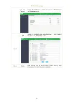
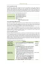
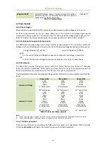
(Register: 6031)
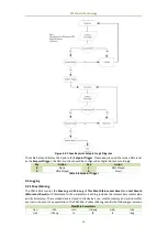
predicted demand output. A value between 70 and 99 is
recommended for a reasonably fast response. Specify a
higher value for higher sensitivity.
Default=70
Table 4-4 Demand Setup
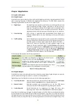
4.3 Power Quality
4.3.1 Phase Angles
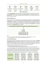
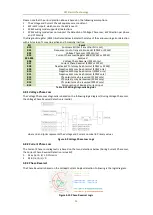
Phase analysis is used to identify the angle relationship between 3-phase Voltages and Currents.
For WYE connected systems, the per phase difference of the Current and Voltage angles should
correspond to the per phase PF. For example, if the PF is 0.5 Lag and the Voltage phase angles are 0.0°,
240.0° and 120.0°, the Current phase angles should have the values of -60.0°, 180.0° and 60.0°.
4.3.2 Unbalance & Sequence Components
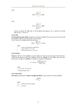
The PMC-53A-E provides Voltage and Current Unbalance measurements. The calculation method of
Voltage and Current Unbalances is based on the ratio of Positive and Negative Sequence Components.
Voltage Unbalance=
V2
V1
×100%
Current Unbalance=
I
2
I1
×100%
where
V1, V2 are the Positive and Negative Sequence Components for Voltage, respectively.
and
I1, I2 are the Positive and Negative Sequence Components for Current, respectively.
4.3.3 Harmonics
The PMC-53A-E provides Voltage and Current with THD, TOHD, TEHD and up to the 31
st
individual
harmonics analysis. Additionally, TDD, K-Factor, and Crest Factor for Current are provided as well. All
harmonic parameters are available via the Front Panel or through communications.
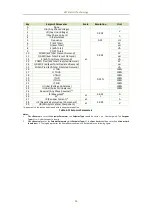
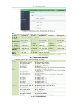
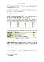
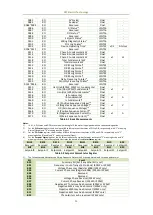
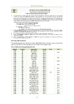
The following table illustrates the available Voltage and Current Harmonics measurements on the PMC-
53A-E.
Phase A/AB
Phase B/BC
Phase C/CA
Harmonic-Voltage
THD
THD
THD
TEHD
TEHD
TEHD
TOHD
TOHD
TOHD
2
nd
Harmonics
2
nd
Harmonics
2
nd
Harmonics
…
31
st
Harmonics
31
st
Harmonics
31
st
Harmonics
Harmonic-Current
THD
THD
THD
TEHD
TEHD
TEHD
TOHD
TOHD
TOHD
TDD
TDD
TDD
TEDD
TEDD
TEDD
TODD
TODD
TODD
K-Factor
K-Factor
K-Factor
Crest Factor
Crest Factor
Crest Factor
2
nd
Harmonics
2
nd
Harmonics
2
nd
Harmonics
…
31
st
Harmonics
31
st
Harmonics
31
st
Harmonics
Table 4-5 Harmonic Measurements
Notes:
1)
When the wiring mode is 1P2W L-L or 1P2W L-N, the harmonic measurements for Phase B/BC and C/CA are invalid.
2)
When the wiring mode is 1P3W, the harmonic measurements for Phase C/CA are invalid.
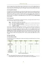
4.3.3.1 THD & Fundamental
There are two methods for calculating the THD, which are based on Fundamental (THDf) and RMS
(THDr). Fundamental is defined as the lowest frequency of a periodic waveform.

