CET Electric Technology
51
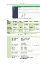
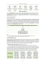
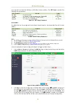
Figure 4-5 Example of a Test Email
3.
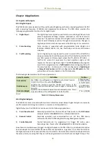
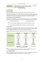
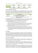
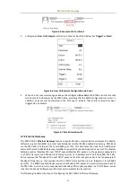
Configure an Over ULL Setpoint via the Front Panel as illustrated below. Set Trigger1 as Email.
Figure 4-6 Over Ull Setpoint Configuration via Panel
4.
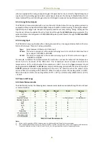
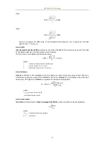
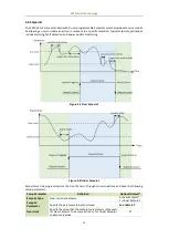
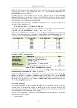
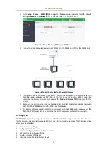
When the ULL measurement goes above the configured Over Limit of 99.70Vac, an Alarm Email
will be sent to the Receiver by the PMC-53A-E, providing that the SMTP configuration is correct. In
addition, an event will be recorded in the SOE Log to indicate that an Alarm Email has been
triggered by a Setpoint.
Figure 4-7 Email Alarm Results
4.7.3 Ethernet Gateway
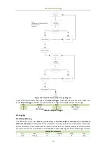
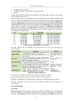
The PMC-53A-E’s Ethernet Gateway feature supports Modbus communications between the Master
Software (e.g. PecStar iEMS) on a Local Area Network and other RS485-enabled devices (e.g. PMC-53A)
via the PMC-53A-E’s Ethernet (P2) and RS485 port (P1). This eliminates the need for an additional,
external Ethernet-to-RS485 Gateway, simplifies the overall network design and saves cost. The Master
Software sends a “Modbus RTU over TCP/IP” packet (Modbus RTU packet, i.e. the payload, encapsulated
in a TCP/IP frame) to the PMC-53A-E’s Ethernet port at its IP Address and IP Port No. 6000. The PMC-
53A-E receives this “Modbus RTU over TCP/IP” packet at its Ethernet port, extracts the “encapsulated”
Modbus RTU packet, i.e. the payload, from the TCP/IP frame and then in turn forwards it to its RS485
port (P1). The RS485-enabled device receives the Modbus RTU packet and sends its response back to
the PMC-53A-E, which in turn encapsulates the Modbus RTU response packet in a TCP/IP frame, sends
it back to the Master Software over Ethernet and completes the transaction.
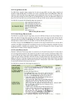
The following illustrates the steps of configuring the PMC-53AE’s Ethernet Gateway:

