CET Electric Technology
52
1)
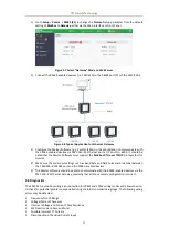
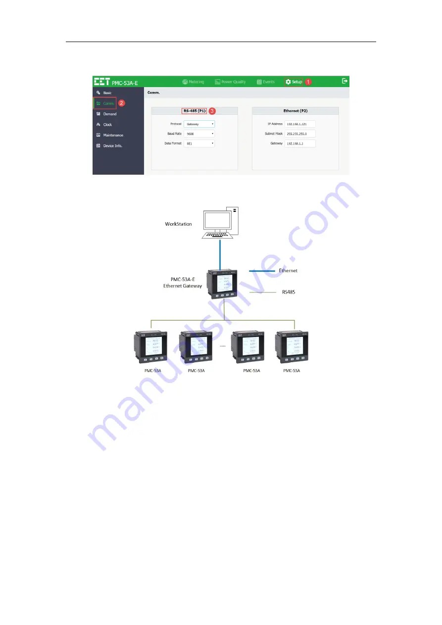
Go to Setup-> Comm.-> RS485 (P1) to change the Protocol setup parameter from the default
setting of Modbus to Gateway, either via the Web Interface or Front Panel .
Figure 4-7 Select “Gateway” Mode on Web Server
2)
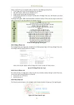
Connect the RS485-enabled devices (i.e. PMC-53A) to the RS485 port (P1) of the PMC-53A-E.
Figure 4-8 Typical Application for Ethernet Gateway
3)
Configure the Master Software (e.g. PecStar iEMS) on the WorkStation to communicate with
the RS485-enabled devices via PMC-53A-E’s Ethernet port at IP port No. 6000. It should be
noted that the Master Software must support the Modbus RTU over TCP/IP protocol for this
to work.
4)
Make sure the serial port settings such as Baud Rate and Data Format are identical between
the PMC-53A-E’s RS485 port and the RS485-enabled devices.
5)
The Master Software should be able to communicate with the RS485-enabled devices via the
PMC-53A-E’s Ethernet Gateway, providing that all the necessary configuration is correct.
4.8 Diagnostics
The PMC-53A-E provides wiring error detection for 3P4W and 3P3W wiring modes and allows the user
to check for potential problems, especially during the initial commissioning stage. The following wiring
errors may be detected:
Frequency Out-of-Range
Voltage/Current Phase Loss
Incorrect Voltage and Current Phase Sequence
kW Direction per phase and Total
Possible Incorrect CT Polarity
Disconnection of Residual Current Input

