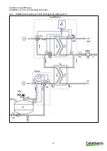
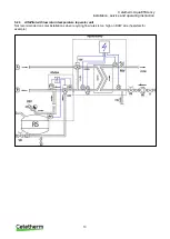
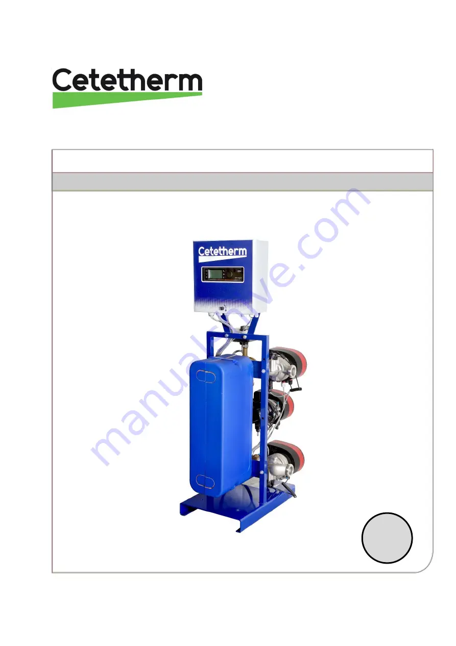
background image

Doc-1388 1810 


Cetetherm AquaEfficiency


Installation, service and operating instruction 
 Installation, service and operating instruction 

GB 

Summary of Contents for AquaEfficiency EFB112 DD

Page 1: ...Doc 1388 1810 Cetetherm AquaEfficiency Installation service and operating instruction Installation service and operating instruction GB...

Page 2: ...out further notice make changes and improvements to the content in this manual if it is necessary due to printing mistakes wrong information or changes in the hardware or software All these types of c...

Page 3: ...taneous 15 7 2 AquaEfficiency EFB112 EFF76 ID Direct Version Instantaneous 16 7 3 AquaEfficiency EFP3000 ID Direct Version Instantaneous 17 7 4 AquaEfficiency EFP5000 7000 ID Direct Version Instantane...

Page 4: ...5 Trending parameters 49 12 5 1 Display the trend buffer 50 12 6 Point Data 50 Alarm menu 51 Parameter list 52 Factory RESET 53 Modbus 54 16 1 Modbus communication 54 16 2 Connecting multiple Micro 30...

Page 5: ...with double pumps 71 19 5 Setup analog inputs 71 19 6 Relay outputs 72 19 7 Pump settings 73 19 8 Enable disable settings 74 19 9 Grundfos Eye operating indications 75 Exploded views and spare part l...

Page 6: ...llation in plant rooms where the ambient temperature always should be above 0 C Max ambient temperature 40 C Max hyg 85 without condensation When handling the unit make sure the actuator and its wire...

Page 7: ...ith actuator A and leaves through the fitting B Cold water enters at bottom part CW and leaves at the required temperature at high part DHW The primary circuit is equipped with a single or double pump...

Page 8: ...nt the control valve with actuator to operate correctly Check the tightening dimensions of the gasket and plate heat exchanger GPHE see measure table in 18 1 Clean the plate heat exchangers P series A...

Page 9: ...y Cetetherm recommends replacing the traditional mixing bottle by a small buffer tank named STBI that serves as an inertial storage tank and avoids any boiler pumping In case a primary vessel named ST...

Page 10: ...Primary inlet Pt1 Primary vessel temperature sensor B Primary outlet S1 DHW temperature sensor master CW Cold Water inlet S2 Secondary inlet temperature sensor DC Drain valve S3 Primary return tempera...

Page 11: ...tetherm AquaEfficiency Installation service and operating instruction 9 4 2 1 Standard flowchart for Indirect version 4 2 2 Other possible drawing Not recommended for low return temperature applicatio...

Page 12: ...ide In the case PT1 S3 T the primary storage vessel is by passed and heat recovery in the primary storage vessel goes on with help from solar panels or other renewable heating source for example heat...

Page 13: ...Cetetherm AquaEfficiency Installation service and operating instruction 11 5 2 1 AlfaPilot with low return temperature heat transfer unit...

Page 14: ...Cetetherm AquaEfficiency Installation service and operating instruction 12 5 2 2 AlfaPilot with double pass heat exchanger tap water system...

Page 15: ...cy Installation service and operating instruction 13 5 2 3 AlfaPilot with low return temperature tap water unit Not recommended on solar installations when recycling flow rates is too high on DHW side...

Page 16: ...st the primary flow rate and obtain low temperature returns on primary side The leaking flow on secondary side coming from the recycling loop allows S2 sensor to be irrigated and to keep SolarFlow awa...

Page 17: ...Cetetherm AquaEfficiency Installation service and operating instruction 15 Measure sketches 7 1 AquaEfficiency EFB60 EFF52 ID Direct Version Instantaneous...

Page 18: ...Cetetherm AquaEfficiency Installation service and operating instruction 16 7 2 AquaEfficiency EFB112 EFF76 ID Direct Version Instantaneous...

Page 19: ...Cetetherm AquaEfficiency Installation service and operating instruction 17 7 3 AquaEfficiency EFP3000 ID Direct Version Instantaneous...

Page 20: ...Cetetherm AquaEfficiency Installation service and operating instruction 18 7 4 AquaEfficiency EFP5000 7000 ID Direct Version Instantaneous...

Page 21: ...Cetetherm AquaEfficiency Installation service and operating instruction 19 7 5 AquaEfficiency EFP9000 ID Direct Version Instantaneous...

Page 22: ...Cetetherm AquaEfficiency Installation service and operating instruction 20 7 6 AquaEfficiency EFB60 EFF52 DD Indirect Version Semi Instantaneous...

Page 23: ...Cetetherm AquaEfficiency Installation service and operating instruction 21 7 7 AquaEfficiency EFB112 EFF76 DD Indirect Version Semi Instantaneous...

Page 24: ...Cetetherm AquaEfficiency Installation service and operating instruction 22 7 8 AquaEfficiency EFP3000 DD Indirect Version Semi Instantaneous...

Page 25: ...Cetetherm AquaEfficiency Installation service and operating instruction 23 7 9 AquaEfficiency EFP5000 7000 DD Indirect Version Semi Instantaneous...

Page 26: ...Cetetherm AquaEfficiency Installation service and operating instruction 24 7 10 AquaEfficiency EFP9000 DD Indirect Version Semi Instantaneous...

Page 27: ...n differential protection and protection against short circuits and protection over intensity must be installed in the main electric box Earth Ground must be wired to the control box on terminal 3 to...

Page 28: ...Bus terminal 2 Power terminal 3 I O terminal 8 2 1 ModBus terminal 24 25 26 C C ModBus cable shield 8 2 2 Power terminal 230V output to pumps and valves 1 2 3 4 5 6 7 8 9 10 11 12 13 14 15 16 17 18 19...

Page 29: ...0V U1 0V U2 0V U3 0V U4 Sensor Pt1 Relay 1 Actuator Sensor 1 Sensor 2 Sensor 3 Sensor 4 49 50 51 52 53 54 55 56 57 58 59 60 IPSO 1 On Off 0V 0 10V IPSO 1 On Off 0V 0 10V Pump 2 Pompe 2 Pump 4 Pompe 4...

Page 30: ...activate the line or change a highlighted value simply press the wheel Works like an Enter key Press to exit a level and return to the previous menu parameter Works like an ESC key Press to access the...

Page 31: ...an be switched into automatic operation Today function Datapoint value can be overridden for a particular time period within the next 24 hours Datapoint must have a daily time program assigned Time Pr...

Page 32: ...Proceed in the same way to set the month date and time hour minute 9 5 Changing the Date format In the Date Time menu the date format can be changed Choose between the following formats yyyy mm dd mm...

Page 33: ...ove 63 C result in an increased risk of precipitation of lime scaling on the surfaces of the heat exchanger 10 2 Time programs The time programs used in AquaEfficiency are adjusted the same way The ti...

Page 34: ...ng by pressing the wheel b Add a new time or set point choose c To delete a time or set point choose In this example the set point is 60 C at 22h00 You can choose to reduce the temperature during the...

Page 35: ...ture change a period of the day with a different setting When the change period has expired the temperature set point goes back to standard time schedule program NOTE Cetetherm do not recommend this i...

Page 36: ...he temperature measured by S3 T_Primary_Inlet Read Only The temperature measured by S4 option T_Renewable1 Read Only The temperature measured by Pt1 Solarflow AlfaPilot configuration T_Renewable2 Read...

Page 37: ...layed decimals on Modbus values 1 integer value eg 58 C 10 1 decimal e g 583 10 58 3 C 100 2 decimals e g 5836 100 58 36 C Relay 1 function 2 1 0 7 0 No action 1 General Default GD 2 High temp Alarm H...

Page 38: ...ect I_Time AquaFirst 15 0 200 sec P to be less reactive P to be more reactive be careful of pumping effect D_Time AquaFirst 2 sec 0 200sec P_Band AquaEff 80 0 P 200 C P to be less reactive 200 to 200...

Page 39: ...rimary pump is the minimum of the signal coming from S1 and the signal coming from the T S3 S2 Parameter Factory Default Setting Optional setting Description Delta T S3 S2 15K 0 100 C keep around 25 D...

Page 40: ...0 10pm and 15 C between 22h00 10pm and 6h00 6am the next day To change this time program settings see 10 2 Time programs 4 Heat Curve curvature Do not change the heat curve curvature it is a factory s...

Page 41: ...thorized period when thermal treatment is OFF in the clock program Parameter Factory Default Setting Optional setting Description ThTr_Setpoint 70 C Usual value ThTr_Activated NS 0 Auto 1 2S Off Off O...

Page 42: ...ll in operation during the Eco function Booster NOTE This function require a second primary pump If the DHW temperature is dropping faster than Booster Gradiant the second primary pump is activated to...

Page 43: ...1 If diff reached at this time pump shift 2 Don t care of Cycling day hour P12 Cycling Period 0 0 None 1 Daily 2 Weekly 3 Monthly P12 Cycling day 1 From 1st to 31st Available only if P12 Cycling Perio...

Page 44: ...oint relative to Srenewable2 Pt2 and regulation around this set point via AO4 signal output Valve No 2 SP_Distrib_Intern 70 C Internal Setpoint for Pt2 if External_Dist_SP Intern SP_Distrib_Ext 65 C E...

Page 45: ...5 2 ByPass function Some condensing boilers do not accept too low return temperatures or too high primary inlet temperatures differentials AquaEfficiency return temperature can be around 25 C at minim...

Page 46: ...g Optional Setting Description Start AutoTest 0 0 1 Set 1 to start auto test When finished the value goes back to zero Pump_Fault_Reset Off Off On Pump time test 4 sec 1 60 sec The time each pump is a...

Page 47: ...larm menu 11 17Clear alarm menu Accessing the Clear Alarm menu requires login at Technician level All alarms are cleared the same way Parameter Factory Default Setting Optional Setting Description Hig...

Page 48: ...ician level NOTE To change the password you need the password for the Technician level level 3 1 Press key to access to Service Menu go to Login Installer press the wheel 2 Enter the current password...

Page 49: ...4 S1 Menu Secondary Outlet TSP_Amb See 11 8 S5 Menu Outdoor Temperature Multi Pulse See 11 15 230V Triac menu Therm treatment See 11 9 Thermal Treatment Menu Point Data Internal parameters I O visual...

Page 50: ...ue 2 Select Operating Hours in the menu The first time you enter this menu the list is empty 3 To add a variable to trend choose 4 Mark one variable to follow and press the wheel 5 Validate the variab...

Page 51: ...utlet temperature S1 6 Validate the variable by ticking in the Trend Log box If this box is empty the variable is in the list but it is not record There are two different ways to record a Only the tem...

Page 52: ...he variable to display S1 in this case and press the wheel Date time and temperature at the time can be read For example on 21st of September at 14h22 was the temperature in S1 58 C 12 6 Point Data Fr...

Page 53: ...mportant alarms like high temp Non Critical Alarms Lists all non critical alarm condition These alarms are more information like power failure For example in the alarm buffer you can read 15 52 SAFETY...

Page 54: ...rm on S1 sensor 0 1 29 Fouling_Alarm Fouling heat exchanger Alarm 0 1 30 Ret_High_Alarm High temperature alarm on S2 0 1 31 ThermTr_Alarm Thermal treatment failed 0 1 32 SAFETY_FCT The safety function...

Page 55: ...r 5 seconds 2 Rotate the wheel select the last line program name with a star at the end 3 Press the wheel a few seconds and the program will start after 1 minute Settings are now factory settings Note...

Page 56: ...ly labelled 25 and 26 on controller C Bus terminal The connection via shielded cable is not required but can be performed with the terminal 24 For this it is necessary to unscrew the front panel 16 2...

Page 57: ...enu go to Login Installer press the wheel 2 Enter the current password press the wheel to validate 3 Mark Next then press the wheel 4 Select Interface Config 5 Select Modbus 6 Select the variable to c...

Page 58: ...HR_16 BOOL R 0 Off 1 On Synthesis pump s fault Tank_load 44 HR_16 BOOL R 0 Off 1 On Tank loaded 16 bit integer Entier 16 bit SW AL Version 34 HR_16 int16 R Software version PA10_Speed_P1P2 45 HR_16 in...

Page 59: ...ck then replace if necessary Supply wires improperly tightened Check wires re tighten connections Actuator stroke restricted Dismount then clean the valve High alarm condition detected Charging pump s...

Page 60: ...ected devices Scaling of the secondary side will be evidenced by a high pressure drop on the secondary side of the exchanger improper temperature range on the secondary side of the exchanger low tempe...

Page 61: ...ation and position 6 Clean the plates being careful not to damage them Do not use metal implements use a metal free nylon brush or solution of dilute acid in accordance with PHE plate general cleaning...

Page 62: ...ct solutions available depending on the cleaning job to be tackled Use a neutralizing solution such as AlfaNeutra before rinsing The circulator systems and pumps require no specific maintenance action...

Page 63: ...use FU1 FU4 For technical information about the fuses see 18 14 Current limiting fuses 18 5 Pumps number The pumps configuration and connections are factory made In a service situation the correct pum...

Page 64: ...the power terminal in the control box Connection on power terminal Connection on Magna 3 pump N Ph Pump 1 4 5 6 Pump 2 7 8 9 Pump 3 10 11 12 Pump 4 13 14 15 3 Select the pump type On the right side o...

Page 65: ...connect to correct polarity Connection on I O terminal Connection on Magna 3 pump 0V 0 10V IN Connect and IN Pump 1 26 27 Pump 2 53 54 Pump 3 32 33 Pump 4 59 60 Once pump is electrically wired rememb...

Page 66: ...20K 2 wires 47 48 S5 7 Outdoor temp sensor heating application only or AquaEfficiency combined with an AlfaPilot unit NTC20k 2 wires 68 69 Sensor DIP switch pos no Description Connection on I O termin...

Page 67: ...st added PT1 You get AlfaStore A AA also called AlfaPilot On Off 3 if added both Pt1 and Pt2 You get a AlfaPilot AP AlfaPilot Inverted 1 0 1 application AlfaPilot SP distrib 0 0 1 Set to 1 if an Exter...

Page 68: ...s either Internal OR External Internal Calculated setpoint is the maximum of SP_Distrib and calculated setpoint of an heat curve issued from S5 External The setpoint is written in the parameter SP_Dis...

Page 69: ...86 480x540x1450 EFF76 EFB112 2 21 A 376 W 3 68 A 556 W 135 590x660x1450 EFP3000 2 07 A 193 W 2 68 A 267 W 191 505x850x1315 EFP5000 2 07 A 193 W 2 68 A 267 W 199 505x850x1315 EFP7000 EFP9000 2 55 A 45...

Page 70: ...is started at the first startup After the startup guide the four main menus will appear in the display The startup guide will guide you through the general settings of the pump such as language date...

Page 71: ...t date 10 Press OK 11 Press OK to start setting and select digit with and adjust with 12 Press OK to save 13 Press to return to the menu Set date and time 14 Select the line Select time format 15 Pres...

Page 72: ...om Home to Assist 2 Select the line Assisted pump setup 3 Go to the submenu Select control mode 4 Select the line Constant curve 5 Press OK to save 6 Go to the submenu Adjust setpoint press OK to star...

Page 73: ...s OK 4 Go to submenu Select multi pump function 5 Select the line No multi pump function 6 Press OK to save the setting 7 Press to see settings summary 8 Press OK to confirm and enable 19 5 Setup anal...

Page 74: ...nal 7 Select the line 0 10V 8 Press OK to save the setting 9 Press to see settings summary 10 Press OK to confirm and enable 19 6 Relay outputs 1 Navigate from Home to Settings 2 Select the line Relay...

Page 75: ...e from Home to Settings 2 Select the line Operating mode 3 Press OK 4 Select Normal 5 Press OK to save the setting 6 Return to the main menu Settings 7 Select the line Setpoint influence 8 Press OK 9...

Page 76: ...19 8 Enable disable settings In this display the possibility of making settings can be disabled for protective reasons 1 Navigate from Home to Settings 2 Select the line General settings 3 Press OK 4...

Page 77: ...running Two opposite green indicator lights permanently on Power on Pump not running One yellow indicator light running in the direction of rotation of the pump Warning Pump running One yellow indicat...

Page 78: ...s too high No Check the winding resistance Internal fault 72 84 155 157 Warning alarm Internal fault in the pump electronics Yes Replace the pump or call GRUNDFOS SERVICE for assistance Overvoltage 74...

Page 79: ...CLA220062 1 1 2 F Non return valve for AquaEfficiency 85 MOT21272 Actuator ML7430E1005 0 10V 15s for V5833 142 KITCOR21261 Kit body 3PV DN32 Honeywell V5833A2100 3 gaskets included 9 SOU29011 Safety v...

Page 80: ...l logo 85 MOT21272 Actuator ML7430E1005 0 10V 15s for V5833 98 KITCOR21262 Kit body 3PV DN40 Honeywell V5833A2118 3 gaskets included 9 SOU29011 Safety valve Male DN 15 10 Bar For URANUS TWHs 10 SON302...

Page 81: ...ate M6 H 316 0 5 EpdmFF endplate 134 POM2025055 Pump MAGNA3 40 60 F 1 230 135 POM2025155 Pump MAGNA3 D40 60 F 1 230 138 POM2025058 Pump MAGNA3 40 120 F 1 230 139 POM202518 Pump MAGNA3 D40 120 F 1 230...

Page 82: ...Cetetherm AquaEfficiency Installation service and operating instruction 80 Commissioning report...

Page 83: ...Cetetherm AquaEfficiency Installation service and operating instruction 81 Declaration of conformity...

Page 84: ...or assessment unless written agreement to proceed otherwise has been obtained from Cetetherm The results of the assessment can only state whether the terms of the warranty apply Exclusion factors Non...

Page 85: ......

Page 86: ......

Reviews: