background image

Cetetherm Midi Wall TA 

Installation, service and operating instruction


12 


5  Electrical installation 

5.1  General 

The wiring in Midi Wall conforms to the applicable rules for CE marking and has undergone electrical safety 

testing and function testing. For permanent installation must the substation be connected to an all-pole isolated 

switch. This must be done by a duly qualified electrician. 

The substation must be connected to a grounded power outlet. 

6  Pump settings and capacity 

6.1  General 

Mini Wall is equipped with two circulation pumps, one for the hot water circulation, DHWC-pump, and one for 

the heating circuit. 


The DHWC pump is a speed-controlled, high-efficiency pump. 


The circulation pump for heating circuit is a pressure-controlled pump. The pump for heating circuit is available 

in two different models. 

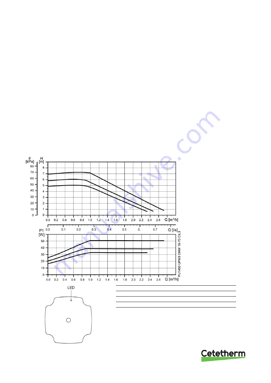
6.2  DHWC pump Grundfos UPM3 DHW 15–70 CIL3, capacity 


Picture 7 


Picture 8 


Green LED 

Red LED 

No external control 


External control 

1


Alarm 


1)

  12 flashes per second 

Summary of Contents for Midi Wall TA

Page 1: ...DOC1364 Rev 11 03 2021 Installation service and operating instruction Cetetherm Midi Wall TA Heating and domestic hot water substation for apartment houses 10 30 apts ...

Page 2: ...hanges and improvements to the content in this manual if it is necessary due to printing mistakes wrong information or changes in the hardware or software All these types of changes will be included in future release of the manual For additional online information and manual QR code ...

Page 3: ...pump Grundfos Magna3 25 100 settings and capacity 15 6 4 1 Heating circuit pump Grundfos Magna3 25 100 capacity 15 6 4 2 Grundfos Eye operating indications 15 7 Service instructions 16 7 1 Tap water service instructions 16 7 1 1 Tap water too cold 16 7 1 2 Tap water too warm 16 7 1 3 Hot water temperature unstable 16 7 1 4 Nosie in the DHWC system 17 7 2 Heating system service instruction 17 7 2 1...

Page 4: ...ling the safety thermostat 26 10 2 3 point or 2 1 point HB metering 26 10 3 Mounting floor stand 27 10 4 Mounting actuator 27 10 5 Balancing valve DHWC 28 11 Technical data and performance 30 11 1 Operation data Midi Wall 70 30 11 2 Operation data Midi Wall 100 31 11 3 Operation data Midi Wall 130 32 11 4 Operation data Midi Wall 160 33 11 5 Technical data 33 ...

Page 5: ...e desired temperature 1 2 Installation Before installation this manual must be read Well planned pipe work make installation very simple The Midi Wall is designed for hanging on the wall 1 3 Long term security All components are adjusted together and undergo thorough function testing in accordance with ISO 9001 2015 quality assurance system For future servicing requirements all components are easi...

Page 6: ...Parts of the Midi Wall may get very hot and should not be touched Before the substation is connected to the electrical supply make sure that the secondary heating system is topped up with water Starting up the system without water will damage the circulation pump When starting up the district heating substation to avoid the risk of scalding make sure that no one draws any hot water until the hot w...

Page 7: ...pes or components Weekly inspection to make sure that the operation of the heating and hot water control systems is stable and that the temperature does not fluctuate Temperature hunting causes unnecessary wear of valves actuators and heat exchangers Every three months check the safety valves and the pressure in the heating system To check the operation of a safety valve turn its wheel knob until ...

Page 8: ... heating 4 Control valve DHW 19 Shutoff valve heat supply 5 Shutoff valve cold water 20 Pump heating 6 Check valve cold water 22 Actuator DHW 7 Filling valve 23 Actuator heating 8 Hose A Heating return 9 Safety valve cold water B Heating supply 10 Shutoff valve DHWC C District heating supply 11 Pump DHWC D DHW 12 Non return valve DHWC E CW 13 Shutoff valve DHW F DHWC 14 Strainer primary in G Distr...

Page 9: ...uction 7 3 1 Schematic diagram main components Picture 2 3 2 Option 3 point HB metering Picture 3 1 Welded filter 2 Shut off valves 3 Manometer clock 4 Sensor pocket energy meter primary in 5 Sensor pocket energy meter primary out 6 Flanged dummy 260mm energy meter ...

Page 10: ...Cetetherm Midi Wall TA Installation service and operating instruction 8 3 3 Measure sketch Midi Wall TA Picture 4 ...

Page 11: ...uld be at least 100 kPa and at most 600 kPa Where the differential pressure is higher a differential pressure controller should be added to the installation Flush heating and hot water systems 4 3 Mounting Mount the substation on a wall with screws and bolts suitable for mounting wall material and substation weight The distance between floor and screw bracket should be 1420 mm Note that distance b...

Page 12: ...ded with actuators see mounting instructions 10 4 Mounting actuator 4 5 Adjustments and settings for start up Open incoming cold water supply and fill the service water and heating circuits bleeding off any trapped air Check the operation and opening pressures of the safety valves Adjust the hot water temperature by having a hot water tap open at normal flow rate for a time Measure the temperature...

Page 13: ... Midi Wall TA Installation service and operating instruction 11 4 7 Connection overview Picture 6 1 Heat Supply G1 1 4 5 DHW G1 2 Heat Return G1 1 4 6 DH Supply DN25 weld 3 CW G1 7 DH Return DN255 weld 4 VVC G1 ...

Page 14: ...ician The substation must be connected to a grounded power outlet 6 Pump settings and capacity 6 1 General Mini Wall is equipped with two circulation pumps one for the hot water circulation DHWC pump and one for the heating circuit The DHWC pump is a speed controlled high efficiency pump The circulation pump for heating circuit is a pressure controlled pump The pump for heating circuit is availabl...

Page 15: ...ll TA Installation service and operating instruction 13 6 3 Heating circuit pump Grundfos UPMXL25 125 180 Auto settings and capacity Picture 9 Pumpkurva MAX Hnom CP1 7 5 m CP2 10 m CP3 12 5 m PP1 8 m PP2 9 5 m PP3 11 m ...

Page 16: ... fast PP3 Flashing slow CP1 Flashing slow CP2 Flashing slow CP3 Picture 10 LED indication of the curve setting 6 3 1 Changing pump curve setting Picture 11 Serial curve setting 1 Push the button for two seconds Pump goes to setting mode LED starts flashing 2 With each push the setting changes LED 1 2 3 are permanently on and then the control curve and mode is changed 3 Flashing mode Fast Proportio...

Page 17: ...re 12 6 4 2 Grundfos Eye operating indications Grundfos Eye Indication Cause No lights are on The power is off The pump is not running Two opposite green indicator lights running in the direction of rotation of the pump The power is on The pump is running Two opposite green indicator lights are permanently on The power is on The pump is not running One yellow indicator light running in the directi...

Page 18: ...leaning the district heating strainer Hot water valve and or actuator does not work See 8 1 Check the function of the hot water valve and actuator 7 1 2 Tap water too warm Reason Action Hot water valve and or actuator does not work See 8 1 Check the function of the hot water valve and actuator 7 1 3 Hot water temperature unstable Reason Action Pending differential pressure Check available differen...

Page 19: ...ce instruction 7 2 1 Heating system temperature too high or too low Reason Action The heating control equipment may need to be adjusted Check and adjust the heating curve See separate instruction Heating circuit strainer clogged See 9 2 Clean the heating circuit strainer Heating valve and or actuator does not work See 8 2 Check the function of the heating actuator and valve 7 2 2 No heating Reason...

Page 20: ...e Check available differential pressure and the primary inlet temperature The temperature can be checked by means of the energy meter minimum 65ºC or at the district heating medium supply District heating strainer clogged See 9 1 Cleaning the district heating strainer 7 2 5 Heating system often needs topping up Reason Action Leaks in the substation or in the system Check the substation and the sys...

Page 21: ...ally by turning the handle Actuator opens the screw of the actuator moves against the red mark Actuator closes the screw of the actuator moves inwards against the blue mark When the actuator closes it pull the valve spindle in Picture 13 4 Loosen the screws on the brace that holds the actuator to the valve lift off the actuator Note The valve can be very hot A working valve will be fully open 5 Ca...

Page 22: ...r closes it pull the valve spindle in 4 Check the flow rate at the energy meter during break in of the valve If the system is lacking an energy meter disconnect the heating actuator from the valve Picture 16 5 Loosen the screws on the brace that holds the actuator to the valve lift off the actuator Note The valve can be very hot A working valve will be fully open 6 Carefully press the valve spindl...

Page 23: ...tart try starting it by removing the pump motor end nut and helping the pump with the aid of a screwdriver in the notch on the engine shaft 2 Use a short screwdriver If the pump is difficult to access disconnect the heating actuator 3 Connect the power supply to the pump and try to start again 8 4 Check the volume take up and pressure equalizing of the expansion vessel Check the expansion vessel f...

Page 24: ...rt with DH supply and then the return line to avoid pollutions in the system Open the valves slowly to avoid pressure surges 1 Disconnect the power supply to the substation 2 Close the shut off valves 3 Use a wrench and release the strainer holder and remove the cartridge 4 Clean the strainer in water and refit the cartridge Screw the strainer holder with a momentum of 10 20 Nm 5 Open the shutoff ...

Page 25: ...sure using the DHWC safety valve After finishing repair fill up the hot water circuit and vent Open the shutoff valves start with DH Supply and then DH return to avoid pollutions in the system Open the valves slowly to avoid pressure surges Check the DHWC circulation Change the complete pump or just the pump motor 1 Disconnect the power supply to the substation disconnect the power cable to the pu...

Page 26: ...o avoid pressure surges Change the complete pump or just the pump head 1 Disconnect the power supply to the substation and the pump 2 Close the shut off valves 3 Choose alternative a or b a When changing the complete pump release the brass nuts with a wrench and replace the pump Connect the pump cable b Only changing the pump head Loosen the screw in the clamp that holds the pump head and pump hou...

Page 27: ...ndle on the actuator to stop the motor 2 Loosen the screws on the brace that holds the actuator to the valve lift off the actuator Note The valve can be very hot Picture 24 3 Use a wrench to remove the control valve Note the arrow direction on the valve 4 Mount a new valve and take especially care to the arrow direction 5 Mount the actuator on the valve slide the actuator onto the valve neck thus ...

Page 28: ...e safety thermostat electrical box on the mounting plate 3 Connect the new power supply cable from the electrical box to the circulation pump 4 Reconnect the existing power supply cable to the connection on the electrical box 5 Attach the thermostat to the pipe for heating supply 6 Set the correct maximum temperature value for the thermostat 7 Attach all electrical wires with the necessary number ...

Page 29: ...should be 1330 mm Note that distance between screws are 400 mm Picture 28 Picture 29 10 4 Mounting actuator 1 Mount the actuator on the valve slide the actuator onto the valve neck thus making the square nut on the valve spindle fit into the groove on the cross bar Then slide the brace into the groove on the valve neck and secure the nuts 2 Remove the actuator lid an attach the wirings 3 Raise the...

Page 30: ...urns In this example 2 3 turns 3 Using a 3 mm Allen key turn the inner spindle clockwise until stop 4 The valve is now set To check the setting Close the valve the indicator shows 0 0 Open it to the stop position The indicator then shows the set value in this case 2 3 Picture 32 The diagram shows the pressure drop for different settings and flow rates Four turns correspond to fully opened valve Pi...

Page 31: ...Cetetherm Midi Wall TA Installation service and operating instruction 29 Picture 34 recommended area 25 dB A 35 dB A ...

Page 32: ... 53 2 6 1 47 15 0 100 43 40 70 67 5 60 40 1 19L 1 20L 0 30 0 9 0 54 2 3 100 43 40 80 26 60 40 1 19L 1 20L 0 11 0 2 0 16 0 2 100 36 33 40 33 08 42 60 40 1 19L 1 20L 0 16 0 3 1 45 15 0 CB60 40L 2 Temperature program C DHW Capacity CB Plates Plates Plates Flow P dPp Flow S dPs kW type no primary secondary l s kPa l s kPa 80 23 10 60 19 1 157 60 40 1 10 1 9 2 10 L 0 62 23 0 0 75 29 9 80 23 10 60 16 1 ...

Page 33: ...2 6 100 43 40 80 33 9 60 50 1 24 L 1 25 L 0 15 0 2 0 20 0 3 100 36 33 40 33 1 50 8 60 50 1 24 L 1 25 L 0 19 0 3 1 75 15 0 100 33 30 60 109 60 50 1 24 L 1 25 L 0 41 1 2 0 88 4 1 CB60 40L 2 Temperature program C DHW Capacity CB Plates Plates Plates Flow P dPp Flow S dPs kW type no primary secondary l s kPa l s kPa 80 23 10 60 19 1 157 60 40 1 10 1 9 2 10 L 0 62 23 0 0 75 29 9 80 23 10 60 17 1 113 60...

Page 34: ...2 9 100 43 40 80 41 5 60 60 1 29 L 1 30 L 0 18 0 2 0 25 0 3 100 36 33 40 33 06 58 47 60 60 1 29 L 1 30 L 0 22 0 3 2 01 15 0 100 33 30 60 133 60 60 1 29 L 1 30 L 0 50 1 4 1 07 4 5 CB60 40L 2 Temperature program C DHW Capacity CB Plates Plates Plates Flow P dPp Flow S dPs kW type no primary secondary l s kPa l s kPa 80 23 10 60 19 1 157 60 40 1 10 1 9 2 10 L 0 62 23 0 0 75 29 9 80 23 10 60 18 1 134 ...

Page 35: ... 43 40 70 144 60 80 1 39L 1 40L 0 63 1 0 1 16 3 3 100 43 40 80 56 60 80 1 39L 1 40L 0 24 0 2 0 34 0 3 100 36 33 40 33 0 57 60 80 1 39L 1 40L 0 22 0 2 1 96 9 1 100 33 30 60 133 60 60 1 29 L 1 30 L 0 50 1 4 1 07 4 5 CB60 40L 2 Temperature program C DHW Capacity CB Plates Plates Plates Flow P dPp Flow S dPs kW type no primary secondary l s kPa l s kPa 80 23 10 60 19 1 157 60 40 1 10 1 9 2 10 L 0 62 2...

Page 36: ...Cetetherm AB Fridhemsvägen 15 372 38 Ronneby Sweden www cetetherm com ...

Reviews: