


26
NE
MESYS XL Manual
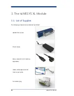
5.
Set Up & Operation
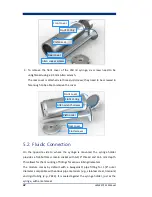
5.1.
Syringes
The
NE
MESYS XL module must only be used with those syringes that have been
developed especially for this module; other syringes may not withstand the
applied forces applied by the pump unit during operation. This may cause
damages to the syringes and the module or injuries to the operator(s).
ATTENTION
Use the
NE
MESYS XL module only with one of the exclusive syringes
especially developed for it by cetoni GmbH.
EPDM is used as the default sealing material in
NE
MESYS XL-compatible syringes.
Additional replacement seals plus seals made from FKM and NBR are supplied
with every module. Other materials are available on request.
CAUTION
Please ensure that the material of the syringe seal is compatible to the
medium to be actuated. If necessary or recommended, you should use a
seal of another, compatible material.
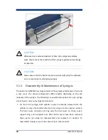
To thoroughly clean the syringes or to change the seal, the XL syringes can be
disassembled. This procedure is explained in detail in section 5.1.3.
5.1.1.
Syringe Configuration
Before a syringe is used for the first time, you must tell the software about that
particular syringe. Only this will ensure that the flow rates and dosed volumes
shown by the software are equivalent to the actual values, respectively; it also
prevents mechanical damages due to wrong stroke distances. The correct


