background image


4


NE

MESYS XL Manual


cetoni GmbH 

Wiesenring 6 

07554 Korbussen 

GERMANY 

Tel.: +49 36602 338-0 

Fax: +49 36602 338-11 


E-mail:  

info@cetoni.de


Internet:  

www.cetoni.de


Summary of Contents for NEMESYS XL

Page 1: ...Original Instruction 1 04 May 2015 Hardware Manual NEMESYS XL ...

Page 2: ...held liable for the payment of damages All rights reserved in the event of the grant of a patent utility model or design The General Terms and Conditions of cetoni GmbH apply Deviating agreements must be in written form Copyright cetoni GmbH automation and microsystems All rights reserved cetoni and NEMESYS are registered trademarks of the cetoni GmbH WINDOWS is a registered trade mark of the Micr...

Page 3: ...s to mixing and combining the software with other software The purchaser may create one back up copy of the software for archival purposes cetoni GmbH reserves the right to alter develop and improve the software or develop new software to replace it cetoni is not obliged to inform the purchaser of any alterations new developments or improvements to the software or make these available to him No le...

Page 4: ...4 NEMESYS XL Manual cetoni GmbH Wiesenring 6 07554 Korbussen GERMANY Tel 49 36602 338 0 Fax 49 36602 338 11 E mail info cetoni de Internet www cetoni de ...

Page 5: ...se 10 2 4 3 Reasonably Foreseeable Misuse 11 2 4 4 Safety Measures 11 2 4 5 Measures for Safe Operation 14 2 4 6 Device Safety Features 14 2 4 7 Device Condition 15 2 5 Warranty Liability 15 3 The NEMESYS XL Module 16 3 1 List of Supplies 16 3 2 Technical Data 17 3 3 Transport Storage 18 3 4 Maintenance 18 3 5 Disposal 19 4 Initial Operation 20 4 1 Software Installation 20 4 2 Device Set Up 20 4 3...

Page 6: ...24 5 Set Up Operation 26 5 1 Syringes 26 5 1 1 Syringe Configuration 26 5 1 2 Mounting of Syringes 27 5 1 3 Disassembly Maintenance of Syringes 30 5 2 Fluidic Connection 32 5 2 1 Initial Swagelok Setup 33 5 2 2 Disassembly 33 5 2 3 Reassembly 34 5 3 Signal Interface 34 5 4 Overload Clutch 36 5 4 1 Overload Procedure 36 5 5 Valve Interface 37 ...

Page 7: ...odule hardware manual 1 0 1 14 01 2012 Changes considering the new 12 pole sensor interface 1 0 2 21 02 2013 Added colors to the 12 pole sensor interface table 1 0 3 06 02 2014 Changes considering the 12 pole sensor interface 1 0 4 06 05 2015 Notes inserted to Pressure Equipment Directive 2014 68 EU ...

Page 8: ... of the present manual We wish you every success when working with the NEMESYS XL module 2 2 Symbols Keywords The following symbols and information boxes are used throughout to aid your navigation TIPP Describes practical tips and useful information to facilitate the handling of the software IMPORTANT Describes important information and other especially useful notes in which no dangerous or damagi...

Page 9: ...NEMESYS XL Manual 9 ATTENTION Indicates a potentially dangerous situation Failure to avert this situation may result in light or minor injuries or damages ...

Page 10: ...ended operation The device complies with critical values according to EN55011 Class 1 Group B The device has passed the tests according to DIN EN 61000 4 4 Burst and DIN EN 61000 4 5 Surge 2 4 Application 2 4 1 General Device Description cetoni s NEMESYS devices are syringe pumps They allow the filling and emptying of syringes based on a relative linear movement between a syringe body fixture and ...

Page 11: ...isks cetoni GmbH advices of the operator s responsibility during use Relevant laws and regulations at the location of use must be observed In the interest of safety operators and users are responsible to adhere to all relevant regulations The device must not be used as a medical product nor in medical applications The device is designed and approved to work in fluidic systems which fall within the...

Page 12: ...d out such as to prevent the danger of tripping The device must only be operated with the safety cover firmly attached Any safety installations must not be tampered with nor rendered in operational Touching any of the devices moving parts during operation must be avoided due to the danger of contusions It is forbidden to use the device in an explosive atmosphere or with potentially explosive mater...

Page 13: ...ssurized Operate the device on safety benches equipped with an emergency stop button The user has to ensure that the application setup includes measures and devices such as safety valves that relieve the system pressure in case of errors or malfunctions Only stainless steel syringes specified for the device are to be used to avoid dangers due to bursting syringes Transport storage and operation of...

Page 14: ...g those of other appliances in close proximity of the device and its cables Portable and mobile communication devices may not be used in closer proximity of the unit or its cables than the recommended safety distance for said devices 2 4 6 Device Safety Features In case of an emergency the device may be switched off at any time using the mains switch rocker switch on the back of the housing or by ...

Page 15: ...lity This device left our company in perfect condition Only the manufacturer is permitted to open the device All guarantee and liability entitlements in particular damage entitlements due to personal injuries are void if the unit is opened by personnel not authorized by cetoni The duration of the warranty is 1 year from the date of delivery It is not extended or renewed due to work carried out und...

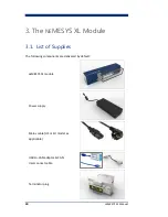
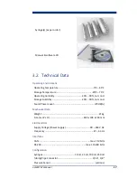
Page 16: ... The NEMESYS XL Module 3 1 List of Supplies The following components are delivered by default NEMESYS XL module Power supply Mains cable US or EU model as applicable USB to CAN adaptor CAN Interconnect cable Terminator plug ...

Page 17: ... Humidity 20 90 not cond Storage Humidity 20 90 not cond Sound Power Level 70 dB A Mechanical Data Weight 21 kg Size L x W x H 600 x 194 x 146 mm Electrical Data Supply Voltage Power Supply 90 264 V AC Frequency 47 63 Hz Interfaces CAN max 1 Mbit s RS 232 max 115200 bit s Configuration Syringes 10 ml 25 ml 100 ml 250 ml Tubing Pipe Connector 1 16 1 8 Pressure Sensor various ...

Page 18: ...pay attention to the details given in chapter 3 1 3 4 Maintenance The device is maintenance free under intended use In case of problems or failure that cannot be solved by the operator or that require opening the device please contact cetoni GmbH to arrange help The device may be opened only by cetoni GmbH or its authorized service personnel failure to comply will void all warranty and claims Pote...

Page 19: ...move heavier stains 3 5 Disposal Old and unused devices must be returned to cetoni GmbH who will ensure proper disposal or recycling of the device in accordance to relevant regulations such as the Electric and Electronic Devices law The device must be decontaminated prior to returning the device as necessary and the completed Contamination Declaration form provided by cetoni ...

Page 20: ...tallation Supplied software and drivers must be installed prior to connecting this or any other cetoni device to a computer Please refer to the accompanying software manual which may be found on the supplied CD for a detailed description IMPORTANT Please follow the instructions and install software and device drivers before connecting the device to your PC 4 2 Device Set Up Place the NEMESYS XL mo...

Page 21: ... be connected and used these are explained in more detail below 4 3 1 Stand Alone Use Connect the USB plug of the USB to CAN adaptor with an USB port USB Type A of your PC Next use the provided D Sub to IXXAT cable to connect the 9pin D Sub plug of the USB to CAN adaptor with the XL module s CAN socket male right above the power socket Attach the terminator plug to the upper CAN socket female of t...

Page 22: ...pment connection cable to connect the power supply with the power socket mains The device may be used with voltages from 90 to 264 V AC alternating current at 47 to 63 Hz 4 3 2 Use with Existing NEMESYS or with QMIX Modules The NEMESYS XL module may be used in combination with other NEMESYS modules or as part of a QMIX system In this case you may not need the USB to USB plug to PC USB to CAN adapt...

Page 23: ...a upper the CAN socket for more details see also next section The connection of the terminator plug and the power supply is as described in section 4 3 1 IMPORTANT Please read and follow the description of the relevant section of the software handbook before connecting operating additional modules and devices 4 3 3 Connecting Additional Modules The XL module provides 24 V DC at 2 A to additional N...

Page 24: ... s RS232 The NEMESYS XL module may be connected to a PC via a conventional RS232 cable the module should be switched off and the power supply interrupted to do this After the connection has been established the module may be reconnected with power and is ready to communicate via RS232 As every NEMESYS module contains the RS232 gateway all connected modules may be controlled via only one RS232 cabl...

Page 25: ...tors Regularly check the device and all cables for damages Never operate a device with damaged cables or connectors Only use supplied original cables ATTENTION Danger of tripping over power and connecting cables Always place cables such as to avoid any danger of tripping ...

Page 26: ...plus seals made from FKM and NBR are supplied with every module Other materials are available on request CAUTION Please ensure that the material of the syringe seal is compatible to the medium to be actuated If necessary or recommended you should use a seal of another compatible material To thoroughly clean the syringes or to change the seal the XL syringes can be disassembled This procedure is ex...

Page 27: ... syringe type has been stored in the software this configuration may be used directly for later setups Scale Volume ml Scale Length mm Piston Stroke mm Max Pressure bar Min Flow µl s Max Flow ml s 10 127 85 130 890 0 18 1 02 25 124 20 128 345 0 47 2 63 100 124 24 128 85 1 86 10 53 250 127 25 130 35 4 53 25 69 5 1 2 Mounting of Syringes 1 Before re mounting a syringe a reference move should be carr...

Page 28: ...ounting the syringe Next remove the safety cover by pulling at its distant end as shown in the picture below until the cover is released 2 To ensure leak tightness with the high pressures involved a metal seal is used between the syringe tip and the syringe holder Place the metal seal ring into the screwed socket of the syringe tip holder and screw in the syringe up to the dead stop using your han...

Page 29: ...Using the wrench an additional one quarter turn should suffice to ensure leak tightness of the connection 4 Connect the syringe piston to the piston holder using the supplied hexagon socket Tighten the screw using a 4 mm Allen key 5 Replace the safety cover by placing its two hooks into the syringe holder Click into place by pushing at the end near the piston head see figure below Hex nut Syringe ...

Page 30: ...and a rear cover The actual configuration differs slightly depending on the size volume of the syringe The following are specific descriptions for each syringe size of how to carry out syringe maintenance 1 For the 10 ml syringe both cylinder covers are directly screwed onto the cylinder remove them either directly or by using a 24 mm spanner wrench The front cover contains an O ring seal the rear...

Page 31: ...lean the support ring behind it the piston tip can be removed using a 13 mm spanner wrench 3 The assembly of the 100 ml syringe is by and large the same as that for the 25 ml syringe There is not support ring at the piston seal and the piston O ring seal may be accessed once the piston has been removed from its cylinder Front O ring Front cover Rear O ring Support ring Support Disc Rear cover Fron...

Page 32: ...r provides a flat bottom screw in socket with G1 4 thread and 16 5 mm depth This allows for the mounting of fittings for various tubing diameters The module comes by default with a Swagelok pipe fitting for 1 8 outer diameter compatible with various pipe materials e g stainless steel titanium and rigid tubing e g PEEK It is sealed against the syringe holder just as the syringe with a metal seal Re...

Page 33: ... against the shoulder rotate the union nut finger tight 2 Mark the union nut at the 6 o clock position 3 Tighten the union nut three quarters turn to the 3 o clock position with an open end wrench 5 2 2 Disassembly 1 Prior to disassembly mark a line along the union nut and fitting body Use these marks to ensure you return the nut to the previously pulled up position 2 Loosen the union nut with an ...

Page 34: ...ENTION You should check all fluidic connections for tightness following each re assembly and at regular intervals during operation 5 3 Signal Interface The NEMESYS XL module comes with a signal interface labeled Sensor at the module s front plate It allows you to connect for example two pressure sensors to be placed at various points within your application The pin assignment of the receptacle is ...

Page 35: ...ue 9 24 VDC Ri 1 8kΩ 6 Digital Output 1 Violet 24 VDC 20 mA Optocoupler 7 Digital Output 2 Grey 24 VDC 20 mA Optocoupler 8 Digital Output 3 White 5 VDC 60 mA Totem Pole 9 Digital Ground Black 10 24 V Out Ret 24 VDC 1 A 11 5 V Out White 5 VDC 150 mA Brown 12 Analog Ground White Black The software configuration of pressure sensors is described in the software manual Please read and follow the descri...

Page 36: ... IMPORTANT You should use a pressure sensor in all your applications to avoid dangerous situations The built in overload clutch is only there as a safety device in case of errors or faults 5 4 1 Overload Procedure 1 Make sure to remove the cause for the overload 2 Following an overload interrupt the overload clutch may re engage automatically the module may then directly be controlled again via th...

Page 37: ...ston fixture the real position of the fixture may deviate from that stored in the software In order to reset the module remove the syringe and carry out a reference move using the software Following this recalibration the module is again ready to be used 5 5 Valve Interface The NEMESYS XL module also features a valve interface It is located on the front plate of the module and allows the direct co...

Reviews: