background image

3 SCPI 

3.3 Instrument subsystem command


40


<StartFreq> Freq Start of sweep.   

Model Range   

1465A [100kHz~3GHz]   

1465B [100kHz~6GHz]   

1465C [100kHz~10GHz]   

1465D [100kHz~20GHz]   

1465E [100kHz~40GHz]   

1465H [100kHz~50GHz]   

1465L [100kHz~67GHz]   

Example: 

:FREQuency:STARt 1MHz Freq Start of Step/Analog Sweep of the signal generator is 1 

MHz.   

Reset status: 

100kHz 


Key Entry: 

Sweep

—>[Step Sweep]/[List Sweep]-> [Freq Start]   

[:SOURce]:FREQuency:STOP <StopFreq>   

Function: 

This command sets Freq Stop of Step Sweep. See the command ―

FREQuency:STARt

‖. 


Setting format: 

[:SOURce]:FREQuency:STOP <val>   

Query format: 

[:SOURce]:FREQuency:STOP?   

Parameter:   

<StopFreq> Freq Stop of sweep.   

Model Range   

1465A [100kHz~3GHz]   

1465B [100kHz~6GHz]   

1465C [100kHz~10GHz]   

1465D [100kHz~20GHz]   

1465E [100kHz~40GHz]   

1465H [100kHz~50GHz]   

1465L [100kHz~67GHz]   

Example: 

:FREQuency:STOP 100MHz Freq Stop of Step/Analog Sweep of the signal generator is 

100 MHz.   

Reset status: 

It is related to the model. For 67GHz model, it is 67GHz. 


Key Entry: 

Sweep

—>[Step Sweep]/[List Sweep]-> [Freq Stop]   

[:SOURce]:FREQuency[:CW|FIXed]:AUTO <State>   

Function: 

This  command  is  used  for  set  frequency  follow-up. When  this  function  is  enabled,  the 

output  CW frequency  of  the  signal  generator  will  change  according  to  the  editing  of 

corresponding  frequency  value  in  the  internal  user  flatness  list.  See  the  commands 

:CORRection:FLATness:PAIR

‖, 

:CORRection:FLATness:FILL:STARt

‖ 

and 

:CORRection:FLATness:FILL:STOP

‖.   

Setting format: 

[:SOURce]:FREQuency[:CW|FIXed]:AUTO ON|OFF|1|0 


Query format: 

[:SOURce]:FREQuency[:CW|FIXed]:AUTO?   

Parameter:   

Summary of Contents for 1465 Series

Page 1: ...1465 series Signal Generator Programming Manual...

Page 2: ......

Page 3: ...1465D signal generator 100kHz 20GHz 1465F signal generator 100kHz 40GHz 1465H signal generator 100kHz 50GHz 1465L signal generator 100kHz 67GHz 1465A V signal generator 100kHz 3GHz 1465B V signal gene...

Page 4: ...riod In order to ship the product back to the manufacturer for repairs the user must pay shipping and handling fees After maintenance and repair the manufacturer will ship the product back to the user...

Page 5: ......

Page 6: ...2 1 6 Programming considerations 26 2 2 Remote interface and its configuration 27 2 2 1 LAN 27 2 2 2 GPIB 28 2 3 I O library 29 2 3 1 Overview of I O library 29 2 3 2 Installation and configuration o...

Page 7: ...2 Example running environment 114 4 1 3 Initialization and default status setting 115 4 1 4 Sending of setting command 116 4 1 5 Reading of instrument status 116 4 2 Advanced operation example 117 4 2...

Page 8: ...he remote control methods of the instrument so that the user can rapidly master the method to control the instrument in a remote way It is further divided into the following three sections remote cont...

Page 9: ...trument test methods Main chapters included in this manual are as follows About This Manual Overview Start Guide Operation Guide Menu Remote Control Fault Diagnosis and Repair Specifications and Test...

Page 10: ...rument with remote control function generally supports four kinds of remote control interfaces i e LAN and GPIB and the type of port supported by the instrument is determined by the function of the in...

Page 11: ...CP IP protocol network via network interface The cable between the computer and the signal generator is a commercial RJ45 cable shielded or unshielded Category 5 twisted pair During data transmission...

Page 12: ...and associated resource string The main control computer uses the respective VISA resource string for instrument identification 2 VXI 11 protocol The VXI 11 standard is based on the ONC RPC Open Netwo...

Page 13: ...transmission rate is limited by the distance between the device system and the computer When GPIB is connected the following points shall be noted Up to 15 instruments may be set up through the GPIB...

Page 14: ...e The command header contains one or more key fields The command with question mark as postfix is a query command Commands are divided into common commands and instrument specific commands that are di...

Page 15: ...SCPIs It guides the equipment to measure and output the signal Response message The response message is a data set that specifies the SCPI format It is always sent from the equipment to the controlle...

Page 16: ...elow SOURce POWer LEVel MAXimum MINimum In the above example the LEVel portion of the command immediately follows POWer with no separating space The portion following LEVel is MINimum MAXimum that is...

Page 17: ...URce LIST DWELl val val A semicolon separates 2 adjacent commands without affecting the current path FREQ 2 5GHZ POW 10DBM White space characters such as space or tab are generally ignored so long as...

Page 18: ...cy REFerence STATe ON FREQuency REFerence STATe 1 FREQ REF STAT ON FREQ REF STAT 1 Each parameter type corresponding to one or more response data types In the case of query a numeric parameter will re...

Page 19: ...0DEG 10 degrees MAXimum maximum valid setting MINimum minimum valid setting UP increase a step DOWN decrease a step Discrete parameter When there are a finite number of parameter values to be set disc...

Page 20: ...e response data can only be returned in the short format with capitalized characters Examples of discrete response data INTernal Amplitude level control mode is internal EXTernal Amplitude level contr...

Page 21: ...nd line contains two commands in which the first one belongs to the MEM subsystem and the second one belongs to the FREQ subsystem If the adjacent commands belong to the same subsystem the command pat...

Page 22: ...STAR STOP 1000000 The returned result may be the current frequency start value because the host program will delay execution of the command If the host program executes the command after receiving it...

Page 23: ...nd WAI or OPC can be used after use of the overlap command to achieve command synchronization In order to synchronously execute other tasks when the computer or instrument is waiting for the completio...

Page 24: ...ery Interrupted message If the return value LSB is equal to 1 this indicates that the overlap command has been executed 2 1 5 Status reporting system The status reporting system will save all operatio...

Page 25: ...nable SRE register constitute the top level register of the status reporting system The STB saves the general working status of the instrument by collecting low level register information 2 ESR SCPI s...

Page 26: ...above register refer to Section 2 1 5 Status Reporting System in this Programming Manual SRE ESE The SRE can be used as an enable part of the STB Similarly the ESE can be used as an enable part of th...

Page 27: ...s part is equal to the value of whole register generally Enable register This part determines whether the associated event bit acts on the final data sum The data bit of each enable part has a And rel...

Page 28: ...hat the instrument has a severe error and the specific error information can be obtained by querying the event status register 6 MSS bit master status summary bit Set the bit if the instrument trigger...

Page 29: ...equency of local oscillator or the reference frequency of any active channel is wrong set this bit 6 Not used 7 If the local modulation setting is wrong set this bit 8 If the instrument is uncalibrate...

Page 30: ...is overloaded set this bit This will cause signal distortion without damaging the instrument and at the same time the user interface will show the prompt message RF overload 3 Input overload If the si...

Page 31: ...s the specific series query method This method is mainly used to quickly obtain the status of one or more instruments connected with the controller in the test system 3 Parallel query The controller c...

Page 32: ...ror As the obtained error cause description is more accurate than the status register the error queue shall be queried in the controller service request handler The error queue shall be frequently que...

Page 33: ...e instrument status e g send RST and then set the desired status 2 Command sequence In general the set and query commands should be sent separately otherwise the returned value of the query command wi...

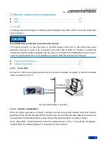
Page 34: ...erator It is not possible to remotely control the instrument via this port Connection Establishment 27 Interface Configuration 27 2 2 1 1 Connection Connect the 1465 series signal generator and the ex...

Page 35: ...rol system and the setting of static IP address rather than DHCP and the access to the host via DNS and domain name server users do not need to modify the subnet mask In the instrument it is fixedly s...

Page 36: ...ed as the intermediate layer of the software between the computer and the instrument hardware equipment composed of function library utility program and tool kit and used as a software code module set...

Page 37: ...can be used such as GPIB and RS 232 the general standard I O software across multiple buses can also be used such as VISA I O 5 Subroutine interface It is a software interface for the instrument driv...

Page 38: ...refer to documents accompanied with the control card and I O Library of your choice The IVI drivers installed are divided into IVI intrinsic function group and instrument class function group basic fu...

Page 39: ......

Page 40: ...he sections about common commands and instrument subsystem commands the commands in sequence are listed first for convenient query and use 3 2 Common command Common commands are used for the control o...

Page 41: ...ed for accomplishing reset function of the signal generator Note for setting only SAV Value Function This command is used for storing the current status of the signal generator in the designated inter...

Page 42: ...hing and RTC Setting format OUTPut BLANking STATe ON OFF 1 0 Query format OUTPut BLANking STATe Parameter State Boolean data is as follows ON 1 Blank is turned on OFF 0 Blank is turned off Example OUT...

Page 43: ...OURce FREQuency REFerence 38 SOURce FREQuency REFerence STATe 38 SOURce FREQuency STEP 39 SOURce FREQuency STARt 39 SOURce FREQuency STOP 40 SOURce FREQuency CW FIXed AUTO 40 SOURce FREQuency CW FIXed...

Page 44: ...pe is set to List mode If the current list is empty the signal generator will prompt the list is empty The signal generator can start sweep only when there is at least one sweep point in the list Exam...

Page 45: ...reference indicator is displayed in the frequency display area In this case the frequency reference value will be subtracted from the set CW output signal For example The current CW output frequency i...

Page 46: ...ency Basic Config Freq Ref Switch SOURce FREQuency STEP FreqStep Function Set the step value of the frequency After setting this value for setting CW frequency of the signal generator please see the c...

Page 47: ...Hz 3GHz 1465B 100kHz 6GHz 1465C 100kHz 10GHz 1465D 100kHz 20GHz 1465E 100kHz 40GHz 1465H 100kHz 50GHz 1465L 100kHz 67GHz Example FREQuency STOP 100MHz Freq Stop of Step Analog Sweep of the signal gene...

Page 48: ...OURce EXTernal COUPling 42 SOURce POWer ALC STATe 43 SOURce POWer ATTenuation 43 SOURce POWer ATTenuation AUTO 43 SOURce POWer LEVel IMMediate AMPLitude 44 SOURce POWer LEVel IMMediate OFFSet 44 SOURc...

Page 49: ...tude ALC Loop Config Search Style Auto Manual Search Out SOURce POWer ALC SOURce Mode Function This command allows users to select ALC Level Control for the signal generator as appropriate including I...

Page 50: ...to Manual For setting auto manual mode of attenuator see the command POWer ATTenuation AUTO The minimum attenuation step set by this command is 5 dB that is users can only set attenuation to 0 dB 5 d...

Page 51: ...lay area and the displayed amplitude value is the actual amplitude power plus the amplitude offset Such amplitude offset does not change the actual output amplitude of the signal generator Only the di...

Page 52: ...yed in the power display area will be the actual CW output power of the signal generator Setting format SOURce POWer REFerence STATe ON OFF 1 0 Query format SOURce POWer REFerence STATe Parameter Stat...

Page 53: ...rmat SOURce POWer ALC BANDwidth BWIDth Parameter AlcBandWidth Discrete data ALC Band is as follows 100Hz 0 ALC Band is 100 Hz 1kHz 1 ALC Band is 1 kHz 10kHz 2 ALC Band is 10 kHz 100kHz 3 ALC Band is 1...

Page 54: ...p from the last point to the first point in current list Setting format SOURce LIST DIRection UP DOWN Query format SOURce LIST DIRection Parameter Direc Discrete data Step Sweep Indirection is as foll...

Page 55: ...ue Setting format SOURce LIST FREQuency val val Query format SOURce LIST FREQuency Parameter Val Frequency of list sweep point Model Range 1465A 100kHz 3GHz 1465B 100kHz 6GHz 1465C 100kHz 10GHz 1465D...

Page 56: ...67GHz Example LIST FILL STARt 300MHz Set Freq Start of List Sweep to 300 MHz Key Entry Sweep List Sweep Freq Start SOURce LIST FILL STOP FreqStop Function This command is used for setting the stop fr...

Page 57: ...nerator stays on the first or the last point of the list This command is only available in the single sweep mode Setting format SOURce LIST RETRace ON OFF 1 0 Query format SOURce LIST RETRace Paramete...

Page 58: ...t sweep points Range 0dBm 100dB 100dB Example LIST FILL POWer 10dB Set the list sweep power offset to 10dB Key Entry Sweep List Sweep All List Ampl Offset SOURce LIST FIll DWELl Val Function This comm...

Page 59: ...put AMPLitude 52 SOURce LFOutput FREQuency 52 SOURce LFOutput FREQuency ALTernate 53 SOURce LFOutput FREQuency ALTernate AMPLitude PERCent 54 SOURce LFOutput NOISe 54 SOURce LFOutput RAMP 54 SOURce LF...

Page 60: ...Frequency1 SOURce LFOutput FREQuency ALTernate Frequency Function This command is used for setting the stop frequency of sweep sine or the frequency 2 of dual sine when LF Waveform is set to SweepSin...

Page 61: ...rcent SOURce LFOutput NOISe Mode Function This command is used for setting signal output types when LF Waveform is set to White noise which includes While noise and Gauss For setting LF waveform see t...

Page 62: ...LF Out LF Waveform SOURce LFOutput STATe State Function This command is used for setting LF Output of the signal generator Setting format SOURce LFOutput STATe ON OFF 1 0 Query format SOURce LFOutput...

Page 63: ...tes sweep from Freq Stop to Freq Start Setting format SOURce SWEep DIRection UP DOWN Query format SOURce SWEep DIRection Parameter Direction Discrete data Step Sweep Indirection is as follows UP Forwa...

Page 64: ...top frequency of step sweep see the commands FREQuecny STARt FREQuenct STOP Setting format SOURce SWEep STEP value Query format SOURce SWEep STEP Parameter FreqStep Frequency step of step sweep Range...

Page 65: ...his command is used for setting sweep mode Setting format SOURce SWEep GENeration ANALog STEPped Query format SOURce SWEep GENeration Parameter Mode Discrete data Options for sweep mode are ANALog Ram...

Page 66: ...PULM INTernal JITTered PERCent 62 SOURce PULM INTernal PTRain DATA 63 SOURce PULM INTernal PTRain DELete 63 SOURce PULM INTernal PTRain POINts 64 SOURce PULM INTernal PTRain PRESet 64 SOURce PULM INT...

Page 67: ...Parameter DelayTime Pulse delay time of pulse modulation Non Trig Mode 0s 0ns 42 000000000s Trig Mode 0s 100ns 42 000000000s Example PULM INTernal DELay 1ms Set pulse delay to 1 ms Reset status 0s Ke...

Page 68: ...command Setting format SOURce PULM INTernal PWIDth val Query format SOURce PULM INTernal PWIDth Parameter PWidth Pulse signal width Range 50 000us 20ns 41 999999990s Example PULM INTernal PWIDth 10us...

Page 69: ...odulation ON OFF SOURce PULM INTernal JITTered MODE Mode Function This command is used for setting the jitter modes of pulse modulation period which include Random and Gaussion At Random mode the puls...

Page 70: ...lsPerd Pulse period of pulse train Range 1ms 0 03us 42s Example SOURce PULM INTernal PTRain DATA 100us 1ms 200us 2ms Set pulse trains with pulse width of 100us and pulse period of 1ms and those with p...

Page 71: ...is empty no operation will be conducted The user may query the points in the current list before deletion operation For the command related to pulse train points see PULM INTernal PTRain POINts Setti...

Page 72: ...ddition pulse width in the list will be a unified value For related commands see PULM INTernal STAGger POINts PULM INTernal PWIDth Setting format SOURce PULM INTernal STAGger INSert index pls_period P...

Page 73: ...taggered EditStagg List Del Current Note for setting only SOURce PULM INTernal STAGger PRESet Function This command is used for deleting all points in Stagg List If there is no staggered point in curr...

Page 74: ...rection is Increase Reset status POS Key Entry Signal LFM LFM Direction SOURce PULM LFM STATe State Function This command is used for setting LFM When LFM is set to ON the signal generator will initia...

Page 75: ...percent The set value is valid only when AM type is set to Linear See the command AM TYPE Setting format SOURce AM DEPTh LINear val Query format SOURce AM DEPTh LINear Parameter AmDepthExp AM depth li...

Page 76: ...ange Dual sine 1kHz 0 02Hz 1 000000000MHz Sweep sine 1kHz 0 02Hz 1 000000000MHz Example AM INTernal FREQuency ALTernate 500kHz Set alternate frequency to 500kHz Key Entry AM Sweep Sinc Freq Stop AM Du...

Page 77: ...s set to Zigzag which includes Zigzag up and Zigzag down For AM signal output waveform see the command AM INTernal SHAPe Setting format SOURce AM INTernal RAMP POSitive NEGative Query format SOURce AM...

Page 78: ...mically greater than that when ALC Loop is turned off and AM index is superior to the index in data manual in NORMal mode AM index is the same as that in data manual Please refer to data index of 1465...

Page 79: ...generator to EXP or Linear AM Depth will be in dB in EXP mode AM Depth will be in percent in Linear mode Setting format SOURce AM TYPE EXPonential LINear Query format SOURce AM TYPE Parameter Mode Di...

Page 80: ...g the internal modulation rate for FM in the signal generator Through this command the first tone can be set when FM waveform is set to DualSinc and the start frequency can be set when FM waveform is...

Page 81: ...e waveform when FM Waveform is set to DualSinc For example if the second tone accounts for 20 of the total waveform power the first tone will account for 80 of the total power output Setting format SO...

Page 82: ...up Reset status POS Key Entry FM M Basic Config FM Waveform Zigzag SOURce FM INTernal SHAPe Mode Function This command is used for setting FM signal output waveform which includes Sinc Square Triangl...

Page 83: ...M Source mode are EXTernal Internal INTernal External Example FM SOURce INT FM Source is set to Internal Reset status INT Key Entry FM M FM Source SOURce FM STATe State Function This command sets the...

Page 84: ...nerator It should be noted that PM Bias varies in different frequency band Setting format SOURce PM DEViation val Query format SOURce PM DEViation Parameter Deviation The relationship between PM Bias...

Page 85: ...is used for setting the second tone when PM waveform is set to DualSinc or the stop frequency when PM waveform is set to SweepSinc For PM waveform see the command AM INTernal SHAPe Setting format SOU...

Page 86: ...sian Gauss Example PM INTernal NOISe GAUS PM noise is set to Gauss Reset status UNIF Key Entry FM M Basic Config PM Waveform SOURce PM INTernal RAMP Mode Function This command is used for setting sign...

Page 87: ...s 10 000us 2s Example PM INTernal SWEep TIME 1s Sweep time of sweep sine for PM signal is 1s Reset status 10 000us Key Entry FM M Sweep Sinc Sweep Time SOURce PM SOURce Mode Function This command is u...

Page 88: ...6 SOURce DM IQADjustment OUTPut STATe 86 SOURce DM IQADjustment OUTPut ATTen 86 SOURce DM IQADjustment OUTPut GAIN 86 SOURce DM IQADjustment OUTPut IOFFset 87 SOURce DM IQADjustment OUTPut UIOFfset 87...

Page 89: ...100 SOURce RADio TTONe ARB STATe 100 SOURce RADio ARB MODE 100 SOURce RADio ARB STATe 101 SOURce RADio ARB SEQuence 101 SOURce RADio ARB SEQuence CLOCk 102 SOURce RADio ARB SCLock RATE 102 SOURce RADi...

Page 90: ...ffset SOURce DM IQADjustment QOFFset Offset Function This command is used for setting Q channel offset of the signal generator in percent The maximum value corresponds to DC 1 5V The minimum resolutio...

Page 91: ...n DM IQADjustment EXTernal IQATten Setting format SOURce DM IQADjustment STATe ON OFF 1 0 Query format SOURce DM IQADjustment STATe Parameter State Boolean data is as follows ON 1 I Q Adjust is turned...

Page 92: ...n Manual mode Reset status 0 Key Entry I Q Attenuation Modulation Attenuation Manual Auto SOURce DM STATe State Function This command enables the internal I Q modulator to ON OFF state Setting format...

Page 93: ...M IQADjustment OUTPut 1 I Q Output Adj is turned on Reset status 0 Key Entry I Q I Q Output Adj I Q Output Adj ON OFF SOURce DM IQADjustment OUTPut ATTen Atten Function This command is used for settin...

Page 94: ...ry I Q I Q Output Adj I Offset SOURce DM IQADjustment OUTPut UIOFfset offset Function This command is used for setting I offset for I Q output adjustment This command will be valid when I Q Output Adj...

Page 95: ...ew Function This command is used for setting Orthority Offset for I Q output adjustment This command will be valid when I Q Output Adj is set to ON For enabling or disabling I Q Output adjustment func...

Page 96: ...urce of real time baseband of the signal generator is set to File this command is used for selecting the data source code file which must be stored under D 1465data user DataSrc with filename extensio...

Page 97: ...ODulation FSK 1MHz FM deviation of FSK is 1MHz Reset status 0 4kHz Key Entry Base Module Type FM Dev SOURce RADio CUSTom MODulation MSK PHASe Phase Function This command is used for setting PM bias of...

Page 98: ...ymbo Bits Symbo Rate BPSK 1 0 00005Msps 50Msps MSK 1 0 00005Msps 50Msps 2FSK 1 0 00005Msps 50Msps OQPSK 2 0 00005Msps 50Msps QPSK 2 0 00005Msps 50Msps 8FSK 3 0 00005Msps 50Msps QAM16 4 0 00005Msps 50M...

Page 99: ...on modulated bit is set to 1 if data bit is different from its previous bit if data bits are the same modulated bit will be set to 0 For example when data bit is 1010 and Differential Encode is turned...

Page 100: ...ommand is used for setting the state of the external trigger delay switch when the Trig Source of the signal generator is set to EXT When the switch is ON the set delay time will be valid For setting...

Page 101: ...the front panel of the instrument BUS 1 The trigger source is from GPIB group execute trigger or triggered when TRG command is received EXT 2 The trigger source is from the trigger input of ports on...

Page 102: ...and load the output Example SOURce RADio CUSTom TRIGger TYPE CONTinuous TYPE FREE Set trigger mode to Continue Auto Reset status FREE Key Entry Base Trigger Trig Style Continue SOURce RADio CUSTom TRI...

Page 103: ...e RADio MTONe ARB STORe mtone1 mtn Save multi tone table to the signal generator multi tone file mtone1 mtn Key Entry Dual Multi Tone Multi Tone Base Config Save Note for setting only SOURce RADio MTO...

Page 104: ...ADio MTONe ARB SETup TABLe FSPacing Parameter FreqSpacing Freq Interval Range 1MHz 100Hz 200MHz Example SOURce RADio MTONe ARB SETup TABLe FSPacing 200kHz Set frequency interval in multi tone table to...

Page 105: ...phase in multi tone table to a fixed value Reset status FIXed Key Entry Dual Multi Tone Multi Tone Base Config Initial Phase SOURce RADio MTONe ARB SETup TABLe PHASe INITialize SEED Mode Function Thi...

Page 106: ...area in user interface of the signal generator will display the indication of IQ Modulate and Multi Tone Setting format SOURce RADio MTONe ARB STATe ON OFF 1 0 Query format SOURce RADio MTONe ARB STAT...

Page 107: ...ARB STATe State Function This command is used for enabling the dual tone modulation function of the signal generator When this function is enabled the main information display area of the signal gener...

Page 108: ...ltiple waveform segments Parameters are composed of file_name waveform reps and M1M2M3M4 File_name refers to the folder where waveform segment file is stored The user specified folder can only be that...

Page 109: ...o ARB SEQuence CLOCk Mode Function This command sets Clock Type when the signal generator is in Arb mode Arb mode allows users to use CUSTom mode only Other modes cannot be set Seq mode enables users...

Page 110: ...odes See the command RADio ARB TRIGger TYPE CONTinuous RADio ARB TRIGger TYPE SINGle RADio ARB TRIGger TYPE SADVance TYPE RADio ARB TRIGger TYPE GATE ACTive Setting format SOURce RADio ARB TRIGger TYP...

Page 111: ...sequence is played no current waveform sequence is replayed until a valid trigger event occurs RESet 2 When Realtime mode is selected no modulation source data will be generated until a valid trigger...

Page 112: ...event is received the system starts to generate the selected modulation source data thereby generating corresponding code pattern data and signals After the current source data is generated the system...

Page 113: ...ght For setting Trig Mode see the command RADio ARB TRIGger TYPE Setting format SOURce RADio ARB TRIGger TYPE GATE ACTive LOW HIGH Query format SOURce RADio ARB TRIGger TYPE GATE ACTive Parameter Mode...

Page 114: ...mple SOURce RADio ARB VCO CLOCk EXTernal Set Trig Source to Bus Reset status LOW Key Entry Arb Trigger Samp Clock SOURce RADio ARB EXternal CLOCk RATE ClockRate Function This command is used for setti...

Page 115: ...ing format MEMory DLEete NAME file_name Parameter FileName String type The user file stored in the signal generator Example MEMory DELete NAME c arb1 seq Delete File arb1 seq in Disk C Key Entry None...

Page 116: ...ust REFerence 109 SOURce ROSCillator ADJust REFerence Val Function This command adjusts the internal reference of the signal generator by setting internal calibration parameters to make the frequency...

Page 117: ...ery of cumulative startup hours of the signal generator DIAGnostic SNUM Function This command is used for reading the system serial number of the signal generator Query format DIAGnostic SNUM Return v...

Page 118: ...escription Mode Discrete data Options for interface language are CHINeses Chinese ENGLish English Example SYSTem DEVice LANGuage ENGLish Set Language as English Reset status Keep current language unch...

Page 119: ...tion will be deleted from the list each time it is queried If there is no error information in the list the user will find the message 0 No ERROR Query format SYSTem ERRor NEXT Return value ErrorInfo...

Page 120: ...the instrument as well as complete the command and data transmission between the computer and the instrument so as to realize the remote control of the instrument By initializing the address string VI...

Page 121: ...integrated development environment NI s PCI GPIB interface card or Agilent s GPIB interface card NI s VISA library or Agilent s VISA library GPIB card Network card Available serial ports COM1 and COM...

Page 122: ...ng global variables ViSession source ViSession defaultRM Const char sourceString VI_FIND_BUFLEN GPIB0 20 INSTR Const sourceTimeout 10000 The constant sourceString represents the instrument descriptor...

Page 123: ...Settings ViStatus status long retCnt Set the frequency to 128 MHz status viWrite source FREQENCY CW 128MHz 18 retCnt Set the amplitude to 10 dBm status viWrite source POW 10dBm 10 retCnt 4 1 5 Reading...

Page 124: ...ust match your host address with the IP address of the signal source The examples of network design in this manual use WINSOCK components to establish socket under VC6 0 include stdafx h include afxso...

Page 125: ...ecking the frequency of GPIB interface This example uses the functions of the VISA library to set the point frequency of the signal source outputting 500 MHZ signals and the power of 2 dBm and query t...

Page 126: ...signal source viPrintf vi FREQ 500MHZ n Set frequency to 500 MHz viPrintf vi FREQ n Check frequency viScanf vi t buff Insert query value into array printf source CW freq is s n buff Display frequency...

Page 127: ......

Page 128: ...operation of the software or hardware of the instrument is defective You can determine the type of the fault according to the error code and then take appropriate measures for troubleshooting The erro...

Page 129: ...nd the format is as follows Error code Error information in error queue Detailed description of error information E g 110 Data out of Range Inputted Parameter out of Lower Bound The information of the...

Page 130: ...r with original packaging materials and put it in a box before the following steps 1 A detailed description of fault symptom should be provided and attached to the signal generator 2 The signal genera...

Page 131: ...air Method 124 8 Packaging and transport of instrument When transporting or handling the instrument for example damage during shipment you shall strictly observe the precautions described in 3 1 1 1 U...

Page 132: ...tion STATe Set modulation master switch 9 SOURce FREQuency CW FIXed Set the signal generator output frequency 10 SOURce FREQuency MODE Set the frequency generation mode 11 SOURce FREQuency MULTiplier...

Page 133: ...POWer REFerence STATe Set the relative power on off 30 SOURce POWer STEP Set the power step 31 SOURce POWer ALC BANDwidth BWIDth Set ALC loop bandwidth 32 SOURce POWer ALC BANDwidth BWIDth AUTo Set A...

Page 134: ...put FREQuency ALTernate AMPLitude PRECent Set the percent of amplitude occupied by frequency 2 in the case of double sine 50 SOURce LFOutput NOISe Set the low frequency output noise type 51 SOURce LFO...

Page 135: ...Rce Set the pulse source 69 SOURce PULM STATe Set the pulse modulation on off 70 SOURce PULM INTernal JITTered MODE Set pulse period jittered mode 71 SOURce PULM INTernal JITTered PERCent Set pulse di...

Page 136: ...ntial AM depth 86 SOURce AM DEPth LINear Set the linear AM depth 87 SOURce AM INTernal FREQuency Set the AM modulation rate 88 SOURce AM INTernal FREQuency ALTernate Set the sweep frequency sine stop...

Page 137: ...RCent Set the percent of amplitude occupied by double sine frequency 102 SOURce FM INTernal NOISe Set the FM noise type 103 SOURce FM INTernal RAMP Set the FM zigzag direction 104 SOURce FM INTernal S...

Page 138: ...source 118 SOURce PM STATe Set the phase modulation on off 119 SOURce DM IQADjustment GAIN Set internal IQ gain balance 120 SOURce DM IQADjustment IOFFse Set the I channel offset value 121 SOURce DM...

Page 139: ...seband filter factor 137 SOURce RADio CUSTom DATA Set the baseband modulation signal data source 138 SOURce RADio CUSTom FILTer Set the baseband filter type 139 SOURce RADio CUSTom MODulation FSK DEVi...

Page 140: ...rol trigger mode 154 SOURce RADio MTONe ARB SETup Select multi tone file loading 155 SOURce RADio MTONe ARB SETup STORe Store multi tone file 156 SOURce RADio MTONe ARB SETup TABLe Set multi tone wave...

Page 141: ...ADio ARB TRIGger TYPE SADVance TYPE Set ARB segmental trigger type 175 SOURce RADio ARB TRIGger TYPE GATE ACTive Set ARB gate trigger mode 176 SOURce RADio ARB TRIGger SOURce Set ARB trigger source 17...

Page 142: ...B address 188 SYSTem COMMunicate GTLocal Set the signal generator to local mode 189 SYSTem DEVice LANGuage Set interface language of device 190 SYSTem COMMunicate LAN IP Set IP address of device 191 S...

Page 143: ...not at the working temperature Loss of lock of reference loop The signal generator s internal loop signal involves loss of lock Loss of lock of decimal loop The signal generator s fractional loop sign...

Reviews: