3672 Series Vector Network Analyzer
Contents
a)
10 MHz Reference Input
As shown in the above figure, the BNC (female) connector can make the analyzer match with the
external reference signal. If the 10 MHz external reference signal is detected on this port, it will be used
as the instrument frequency benchmark to replace the internal frequency benchmark. The 10 MHz
reference input port has the following characteristics:
Input frequency: 10 MHz±1 ppm
Input level: -15 - +20 dBm
Input impedance: 200Ω
b)
10 MHz Reference Output
It can provide the reference signal with following characteristics through the BNC (female)
connector:
Output frequency: 10 MHz±1 ppm
Signal type: Sine wave
Output level: 13 dBm±4 dB into 50Ω
Output impedance: 50Ω
2)
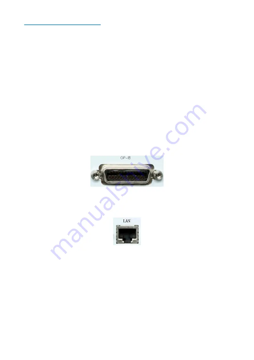
Universal interface bus connector
As shown in the following figure, this is a 24-pin type D female connector conforming to the
IEEE-488 standard. It is used to send and receive the GPIB/SCPI command.
Fig. 2.22 Universal Interface Bus Connector
3)
LAN connector
As shown in the following figure, this is a 10/100/1000BasetT Ethernet connector with a standard
8-pin structure, which can be automatically selected from three data rates.
Fig. 2.23 LAN Connector
4)
USB connector
As shown in the following figure, the jack socket of the connector can be classified into type A
configuration (4 embedded contact: The contact 1 is on the left side) and type B configuration. The type
A configuration connector can be connected with the USB mouse, keyboard or other USB interface
equipment, and there are 4 connectors in the rear panel. The interface characteristics are as follows:
Port 1: Vcc, 4.75 V ~ 5.25 V, max.: 500 mA
Port 2: Data-
Port 3: Data+
Port 4: Ground
The type B configuration connector is mainly used to complete the control function, and the network
device can be controlled through the SCPI to connect with the external computer or remote control
equipment. There is 1 connector in the rear panel.

