background image

Quick Start Guide for 3680A/B Cable and Antenna Analyzer 


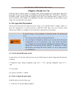
 AC-DC adapter provided together with the instrument must be used if adopting AC power supply. Input of 

adapter is AC power supply with 100~240V, 50/60Hz. 


When  transported  and  carried  by  a  backpack,  the  AC-DC  adapter  should  not  be  connected  with  the 

Analyzer in order to avoid overheating of the instrument. AC-DC adapter has a wide range of input voltage; 

therefore  when  using,  it  should  ensure  the  power  supply  voltage  should  be  within  the  scope  required  in 

Table 2.1. 


Table 2.1 Power Supply Requirements 

Power Supply Parameter 

Applicable Range 

Input Voltage 

100V

240VAC 

Rated Input Voltage 

1.7A 

Operating Frequency 

50/60Hz 

Output Voltage/Current 

15.0V/4.0A 


Operating  voltage  and  frequency  is  subject  to  that  indicated  in  the  nameplate  of 

supplied power adaptor. 


2. Powered by DC power supply 


Voltage: 12V

18V (with battery uninstalled), 15V

18V (with battery installed) 

Current: 2A (at minimum) 


3. Powered by built-in battery 

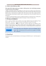
3680A/B can be powered by rechargeable lithium-ion batteries. If left unused for a long time, the battery 

will self discharge, so it must first charge the battery before using it again. Refer to Section 2.6 for battery 

usage details. The basic parameters of batteries provided together with the instrument are as follows: 


Nominal voltage: 10.8V 

Nominal volume ≥7000mAh 


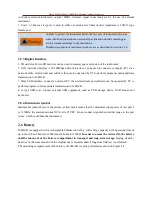
Rechargeable  battery  shall  not  be  exposed  to  fire  and  high  temperatures  (above 

70

),  or  thrown  into  the  fresh  or  salt  water,  and  wetted,  and  shall  keep  away 

from children. 

Rechargeable batteries can be reused, and shall be placed in a suitable container 

to avoid short circuit. The heavy metals such as nickel and chromium contained in 

the battery may pollute the environment, so waste batteries should be placed in a 

dedicated battery recycling bins rather than disposed at will ,. 


Warning 

Warning 

Summary of Contents for 3680A

Page 1: ...3680A B Cable Antenna Analyzer Quick Start Guide China Electronics Technology Instruments Co Ltd...

Page 2: ...parts according to the actual situations This requires user to return the product back to the manufacturer and prepay the postage which will be returned together after maintenance Certificate of Qual...

Page 3: ...Panel 4 2 4 Operating interface 7 2 5 Top Interface 7 2 6 Battery 8 Chapter 3 Typical Application 10 3 1 Calibration 10 3 2 Cable Test 12 3 3 Antenna Test 18 3 4 Universal Devices and Parts Test 19 3...

Page 4: ...nna Analyzer contains chapters as follows Ready for Use This Chapter introduces preparations before operation startup panel introduction battery replacement etc of 3680A B Through this chapter you can...

Page 5: ...to the instrument or unnecessary personal injury To prevent damage to the instrument avoid electric shock fire and personal injury Do not open up the instrument without authorization Do not attempt t...

Page 6: ...aptor 2 Powered by DC power supply Voltage 12V 18V with battery uninstalled 15V 18V with battery installed Current 2A at minimum 3 Powered by built in battery 3680A B can be powered by rechargeable li...

Page 7: ...t may be achieved by grasping the metal casing of instrument grounded or the casing of connector of testing cable 2 2 Startup and utilization Prior to powering 3680A B please perform power supply inst...

Page 8: ...on including calibration mode calibration status ON OFF and selection of calibration kit models Save Recall used for file operations such as store and recall of measurement state store and recall of m...

Page 9: ...atus Physical state of Analyzer Off state Off a The battery has been installed not connected to the power supply b The battery has not been installed not connected to the power supply Constant yellow...

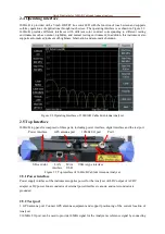
Page 10: ...g Interface of 3680A B Cable Antenna Analyzer 2 5 Top Interface 3680A B top panel is composed of three parts including power interface digital interface and the test port Power interface GPS antenna p...

Page 11: ...transmission to 3680A B 3 Mini USB interface connect an external PC then related tools and software can be operated by PC to perform program control and data transmission to 3680A B 4 A type USB port...

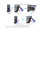
Page 12: ...a Analyzer Figure 2 4 Battery Mounting or Replacement In addition for those dead batteries charging time in OFF state is about 4 hours Pull down battery cover Open battery cover Mount Pull out the bat...

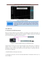
Page 13: ...s mechanical calibration method whose calibration process is as follows 1 Press CAL to enter the calibration menu 2 Select Cal Kit menu then choose the matched model of calibration kit from Select Cal...

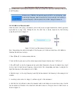
Page 14: ...it measurement Figure 3 3 Completion of Open Calibration Connect the short to the test port and select the Short menu At this time the screen will automatically prompt SHORT Measuring When the SHORT m...

Page 15: ...asurement 3680A B mainly tests RF cable Take the cable with length of 25m radio frequency of 2 1GHz and VSWR of 1 05 as an example this part makes a detailed instruction on test steps of return loss M...

Page 16: ...to step 3 set the stop frequency needed by the measurement the frequency in this example is set to 4GHz 5 According to the Section 3 1 in this Chapter calibrate at port 1 of the instrument 6 After th...

Page 17: ...format of instrument as Cable Loss 3 Press Freq to enter the frequency menu select Start Freq menu then use the numeric keys knob or arrow keys to input the start frequency value and select the corre...

Page 18: ...verage loss of the cable Limit value search process is as follows Press Marker to enter the marker menu and the Marker 1 defaults to be in open state at this time Select Peak menu to place Marker 1 on...

Page 19: ...ss Meas to enter the measurement menu 2 Select DTF Return Loss menu to set the current measurement format to DTF Return Loss 3 Press Freq to enter the frequency menu select Start Freq menu then use th...

Page 20: ...rn loss test connection is as shown in Figure 3 11 Open circuit Figure 3 11 DTF Return Loss Test Connection Diagram 12 Press Marker to enter the marker menu Marker 1 has been turned on at this time Se...

Page 21: ...turn Loss or VSWR as the measurement format of Analyzer 2 Press Freq to set instrument frequency measurement range by contrasting with receiving frequency range of the antenna to be received if the fr...

Page 22: ...1Z05 195 3 4 Universal Devices and Parts Test Addition to cable and antenna test 3680A B can also be used for testing the attenuation cable connectors cable joints etc This part will measure the retur...

Page 23: ...tor are all below 30dB Based on the test data designer can confirm attenuator index by contrasting with design index as shown in Figure 3 16 Figure 3 16 Return Loss Test of 10dB Attenuator 3 5 Test Sk...

Page 24: ...line Users have their own eligibility criteria in batch test In this regard 3680A B provides Limit function for the setting of limit line making it easier to test products Thus when large quantities...

Page 25: ...ction is turned on Analyzer will raise a beep beep alarm through which users can judge whether the product is qualified or not Test curve in Figure 3 20 has exceeded the set limit line Figure 3 20 Ala...

Page 26: ...s recall Users can directly use Cable Model menu in the menu bar of FREQ to enter the interface for cable model selection Then select the corresponding cable model through the touch screen knob or ar...

Page 27: ...on speed of electromagnetic wave in the cable to be measured The smaller the sweep span is the longer the measured maximum distance will be The more the sweep points are the longer the measured maximu...

Page 28: ...re please contact us for return to factory repair If 3680A B fails to start up and self test please press Reset key which makes 3680A B return to a known state If the self test still fails then it mig...

Page 29: ...ems In addition please contact us in time if instrument failure occurs we will provide assistance required Return to factory repair is also supported if necessary Users are forbidden to disassemble th...

Page 30: ...y 1 10 6 10 23 1 10 6 10 23 Frequency Resolution 1kHz 1kHz Effective Directionality 42dB M Cal 35dB Embedded E Cal 42dB 1MHz 6GHz M Cal 36dB 6GHz 8GHz M Cal 31dB 1MHz 6GHz Embedded E Cal 26dB 6GHz 8GH...

Page 31: ...probe 10kHz 18GHz 3680 009 87232 USB continuous wave power probe 50kHz 26 5GHz 3680 010 87233 USB continuous wave power probe 50kHz 40GHz 3680 011 Standby rechargeable lithium ion battery 3680 012 N...

Page 32: ...Quick Start Guide for 3680A B Cable and Antenna Analyzer...

Reviews: