3 Quick Start
3.2 Description of front and rear panels and interfaces
22
①
② ③
④
⑤
⑥
⑦
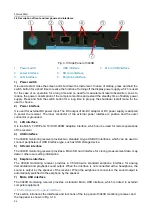
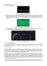
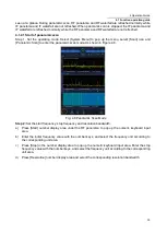
Fig. 3.13 Side Panel of 3943B
1. Power switch
2. power interface
3. LAN interface
4. USB interface
5. SD card interface
6. Earphone interface
7. Micro USB interface
1) Power switch
It is used to start, close the screen and shut down the instrument. In case of startup, press and hold the
switch button for a short time to realize the function of turning off the display power supply, which is used
for the case of no operation for a long time and no need for measurement result observation, so as to
reduce the power consumption of the complete machine and extend the standby time of battery power
supply. Press and hold the switch button for a long time to prop up the shutdown/ restart menu for the
user to choose.
2) Power interface
It is used for external DC power input. The DC output of AC-DC adapter or DC power supply is adopted
to power the receiver. The inner conductor of the external power interface is positive and the outer
conductor is grounded.
3) LAN interface
It is the RJ45, TCP/IP and 10/100/1,000M adaptive interface, which can be used for remote operations
of the receiver.
4) USB interface
The 3943B monitoring receiver provides two standard A type USB2.0 interfaces, which can be used to
connect peripherals of USB interface type, such as USB storage device.
5) SD card interface
The 3943B monitoring receiver provides a Micro SD card interface for storing measurement data, map
data or other user setting information.
6) Earphone interface
The 3943B monitoring receiver provides a 3.5mm/3-wire standard earphone interface for analog
demodulation and playback sound output. When the interface is not connected with a headphone, the
sound is output by the speaker of the receiver. When the earphone is connected, the sound output is
automatically switched to the earphone by the speaker.
7) Micro USB interface
The 3943B monitoring receiver provides a standard Micro USB interface, which is linked to external
computer equipment.
3.2.3 Description of top panel interface
This section introduces the interfaces and functions of the top panel of 3943B monitoring receiver, and
the top panel is shown in Fig. 3.14.


