Chapter XVIOscilloscope Probe (Option)
202
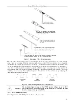
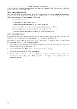
When the P4220 probe is used, the input impedance of the oscilloscope is set to 1M
Ω
, the probe type is set to
voltage, and the probe attenuation is set to ×1000. To avoid the error caused by the probe connection, the probe
should be connected to the function generator with the signal source frequency of about 200Hz and the amplitude
of 20Vpp, so as to keep flat amplitude-frequency characteristics of the oscilloscope by adjusting the compensation
capacitance of the probe.
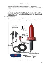
Fig. 16.20 Schematic Diagram of Probe Compensation
Warning:
The maximum input voltage of the P4220 high voltage single end probe is 39kV
(DC+ACpk). Do not exceed this voltage in use. Otherwise, it will cause personal
hazard or injury or damage to the DUTs. When the measured voltage exceeds
30kVDC or 20kV AC, the probe is not suitable for long-term use because the
high voltage measurement source will discharge in the air, causing that the
voltage stabilizing circuit of the high-voltage source fails to respond. There will
be a pulse high voltage instantaneously, which may exceed the rating of this
product and will cause serious damage to this product.
Warning:
When the P4220 high voltage single end probe is tested at a frequency exceeding
40MHz, replace the long ground wire with the crocodile clip in order to achieve a
better frequency response. When the measured voltage exceeds 25kV, install the
attached accessory HI-25, which will obtain a surface distance of 40cm or more
(the insulator must have a surface distance of more than 39 cm during measuring
39KV voltage according to the CE guidelines)
16.7.3 Main Parameters of Probe
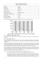
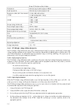
The main parameters of the P4220 probe are shown in the table below.
Table 16.7 P4220 Probe Parameters
Model
P4220
Bandwidth
220Mhz
Attenuation ratio
1/1000
Termination
900M
Ω
Input capacitance
2pF
Maximum input voltage
39kV (DC+ACpk)
Maximum load current
45uA
Signal-to-noise Ratio
>60dB @1kHz
DC signal error
±3% (0-35kV)
Capacitance compensation range
10-35pF
Safety inspection
EN61010-031 CATII
Test cable length
2±0.2 m
Weight
460g
Size
320×80×80 mm
Operating temperature
0-50
℃
Storage temperature
-20-70
℃
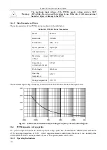
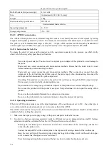
The maximum input voltage-frequency characteristic of the P4220 is shown in the figure below.
Over-compen
sation
Correct
compensation
Insufficient
compensation
Summary of Contents for 4456 Series
Page 10: ...VIII...
Page 55: ...Chapter V Trigger System 45 Fig 5 51 RF Test Signal Example...
Page 69: ...Chapter VII Mathematical Operation 59 Fig 7 10 Advanced Math Example...
Page 71: ...Chapter VIII Display System 61 Fig 8 3 Wfm Palette Menu Fig 8 4 Normal Palette...
Page 72: ...Chapter VIII Display System 62 Fig 8 5 Inverted Palette Fig 8 6 Temperature Palette...
Page 75: ...Chapter VIII Display System 65 Fig 8 12 XY Display Example...
Page 165: ...Chapter XI Protocol Analyzer Option 155 Fig 11 242 1553 Trigger and Analysis Example...

