Chapter XVIOscilloscope Probe (Option)
214
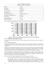
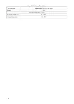
Termination
Between input end and ground: 20MΩ
Input capacitance
Between input end and ground: 1pF
Maximum differential measurement
voltage
1/100: 1.4kV (DC+ACpp)
1/1000: 14kVpp (DC+ACpp)
CMRR
60Hz: >80dB
100Hz: >60dB
1MHz: >50dB
Output voltage (50Ω load)
±7V
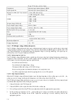
Power adapter output voltage
DC6V, 150mA
Power adapter input voltage
AC100 ~ 240V, 50 ~ 60Hz
Built-in batteries for power supply
4×AA cells
Size
Approximately 245×84×36 (mm)
Weight
500g
Electronic safety specification
IEC1010-1
Environmental characteristics
Operating temperature
0 ~ 50
℃
Storage temperature
-30 ~ 70
℃
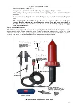
16.12 P7100 high voltage differential probe
The P7100 high voltage differential probe uses a differential input mode and is mainly used for places where high
voltage floating measurements are required. The probe has a bandwidth of 100MHz and is available with 1/100
and 1/1000 attenuations. Its differential mode measurement range is 0.7kVpp and7kVpp. The option can be
purchased by users. The option number is 4456-H19.
16.12.1 Instructions for Safe Use
The P7100 high voltage differential probe is mainly used for places where high voltage floating measurements are
required. To ensure the safety of users and the product and the equipment connected to the product, you shall
strictly observe the following safety operation specifications:
Be careful of electric shocks.
Pay attention to the highest input voltage.
The highest differential voltage is 7kV (DC+ACpp).
Do not use this product in a humid environment or at an explosive risk.
Cut off the output and input ends when opening the box cover of this product.
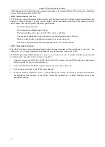
16.12.2 Operating Instructions
When the P7100 high voltage differential probe is used, the input impedance of the oscilloscope is set to 1M
Ω
, the
probe type is set to voltage, and the probe attenuation is set to the same as that of the P7100.
The P7100 high voltage differential probe is easy to use, but users who are not familiar with this product should
read this manual completely before starting the operation:
1
)
Connect the hook to the P7100 input end.
2
)
Connect the BNC at the output end of the P7100 to the oscilloscope.
3
)
Turn on the power switch of the P7100 power adapter and select the appropriate range position.
4
)
Set the oscilloscope impedance to 1M
Ω
, set the probe type to voltage, and set the same probe attenuation as
the attenuation ratio multiple of the P7100. Adjust the oscilloscope
’
s vertical sensitivity knob to the
appropriate position.
Summary of Contents for 4456 Series
Page 10: ...VIII...
Page 55: ...Chapter V Trigger System 45 Fig 5 51 RF Test Signal Example...
Page 69: ...Chapter VII Mathematical Operation 59 Fig 7 10 Advanced Math Example...
Page 71: ...Chapter VIII Display System 61 Fig 8 3 Wfm Palette Menu Fig 8 4 Normal Palette...
Page 72: ...Chapter VIII Display System 62 Fig 8 5 Inverted Palette Fig 8 6 Temperature Palette...
Page 75: ...Chapter VIII Display System 65 Fig 8 12 XY Display Example...
Page 165: ...Chapter XI Protocol Analyzer Option 155 Fig 11 242 1553 Trigger and Analysis Example...

