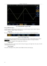
Chapter V Trigger System
24
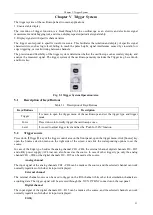
The trigger signal is taken from the AC power input of the oscilloscope. This source can be used to display the
relationship between a signal (such as a lighting device) and a power supply (power supply device). For example,
the waveform of the transformer output of a stable trigger substation is mainly used in relevant measurement of
the power industry.
5.3
Trigger type
The 4456 series oscilloscope supplies users with rich trigger functions, including Edge, Pulse Width, Video, Runt,
Logic, Sequence, Setup&Hold, Rise/Fall Time, HD Video, RS232 Trigger, I2C Trigger, SPI Trigger, CAN Trigger,
LIN Trigger, I2S Trigger, USB Trigger, FlexRay Trigger, 1553 Trigger and Visual Trigger (Area Trigger), which
help users locate events in which they have interest out of complicated sample information.
Edge trigger
Trigger on the Rise or Fall edge of any channel or AUX IN
Trigger type
Press down
【
Trigger
】
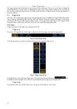
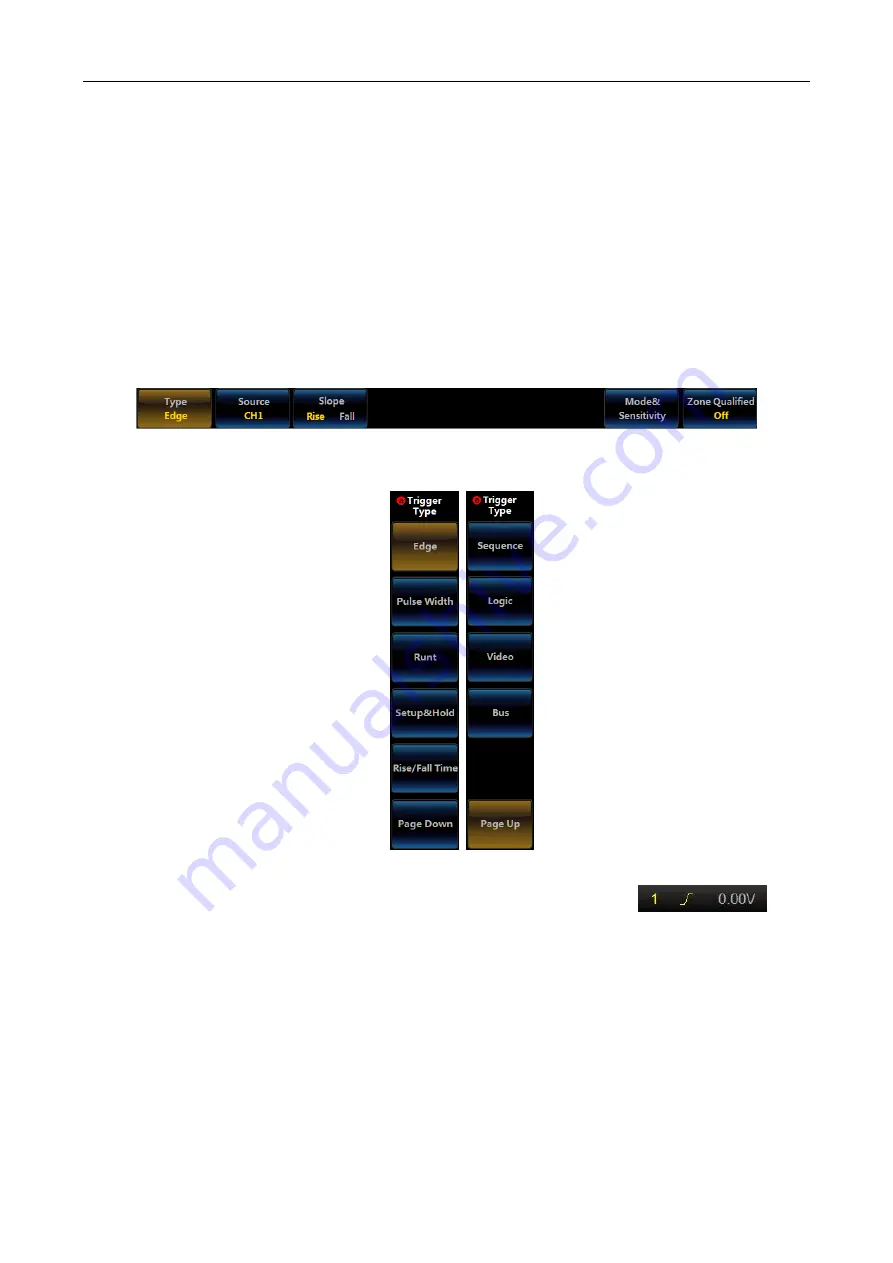
key of the trigger control area on the front panel, and open the trigger menu.
Fig. 5.2 Edge Trigger Menu
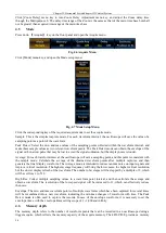
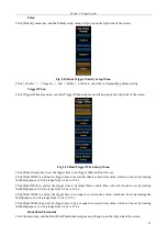
Click [Type] menu key, and the Type menu will pop up on the right side of the screen.
Fig. 5.3 Trigger Type Menu
Click [Edge] key to select the slope trigger type. The relevant edge trigger information
will
be displayed on the top right corner of the screen, including the source, edge type and trigger level.
Trigger source
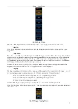
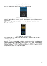
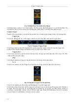
Click [Source] menu key, and the Source menu will pop up on the right side of the screen:
Summary of Contents for 4456 Series
Page 10: ...VIII...
Page 55: ...Chapter V Trigger System 45 Fig 5 51 RF Test Signal Example...
Page 69: ...Chapter VII Mathematical Operation 59 Fig 7 10 Advanced Math Example...
Page 71: ...Chapter VIII Display System 61 Fig 8 3 Wfm Palette Menu Fig 8 4 Normal Palette...
Page 72: ...Chapter VIII Display System 62 Fig 8 5 Inverted Palette Fig 8 6 Temperature Palette...
Page 75: ...Chapter VIII Display System 65 Fig 8 12 XY Display Example...
Page 165: ...Chapter XI Protocol Analyzer Option 155 Fig 11 242 1553 Trigger and Analysis Example...


