Chapter VII Performance feature test
99
adjust the IF bandwidth of the receiver, and ensure that the IF bandwidth is more than twice of
frequency modulation deviation. Then read the test result of frequency modulation deviation and
record it in Table A.17.
17. Spectrum analyzer (tested if any)
A.Input frequency range
a) Test items
The output signal of the test signal generator of the frequency meter is applied for comparison to
test the frequency range of the received signal of the optional spectrum analyzer. The requirement
for this indicator is 2MHz to 1000MHz.
b) Test block diagram and meters
Instrument / equipment:
BNC cable: one (30cm)
c) Test steps
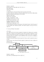
1) Connect the RF input and output end of the tested device as shown in the figure. Start the
instrument and warm it up for 30min.
2) Open the RF source window by pressing the [Transmitter] hard key or pressing the
[Measurement] hard key and setting the instrument menu. Set it as follows.
Port: SWR
Frequency of RF Source 1: 2MHz
RF Source 1Power: -10dBm
RF Source 1: ON
The modulation window must not be opened.
3) Open the spectrum analyzer window by pressing the [Measurement] hard key and setting the
instrument menu. Set it as follows.
Port: ANT
Center: 2.005MHz
sweep width: 10kHz
Reference: 0dBm
resolution bandwidth: 30Hz
4) After scanning, read the peak frequency of the signal with the cursor, and record it in the test
record table A.18.
5) Change the output frequency of RF Source 1 into 1000MHz. Then change the center frequency
of the signal received by the spectrum analyzer into 999.995MHz. Repeat Step 4).
6) If the test frequency error of the tested device is ± (5%×sweep width+25%×resolution
bandwidth), the frequency range conforms to the requirement; otherwise, this the frequency
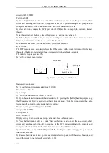
Fig. 7-8 Connection Diagram of Frequency Range Test of Spectrum Analyzer
RF input ANT
RF output SWR
4992A
Rradio Test Set
Summary of Contents for 4992A
Page 1: ...I 4992A Radio Test Set User Manual China Electronics Technology Instruments Co Ltd...
Page 2: ......
Page 5: ......
Page 6: ......
Page 7: ......
Page 23: ...Article I Handling Instructions 11 Article I Handling Instructions...
Page 93: ...81 Article II Technical Specifications...
Page 132: ...Article III Maintenance Instructions 120 Article III Maintenance Instructions...


