Chapter VII Performance feature test
111
2) Set the pulse signal of the function generator as follows:
Waveform: pulse
Amplitude: 1V
Cycle: 400ms
Pulse width: 200ms
3) Open the oscilloscope window of the tested device by pressing the [Measurement] hard key and
setting the instrument menu, and set it as follows:
Time/interval: 50ms
Amplitude/interval: 500mV
Reference position: 4
Trigger: trigger mode: normal
Pules edge: rising
Trigger level: 0V
Trigger position: 0nS
Port setting: DVM
DVM setting: coupling mode: DC
Range: 0.1V to 3V
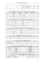
4) Test the pulse width with the cursor function, and record the result in the performance test
record table A.29.
24. Cable test
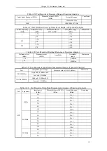
A. Measurement accuracy of standing wave ratio (VSWR)
a) Test items
The standing wave ratio of the tested instrument is measured in the open-circuit and matching
status of the port after calibration.
The indicator requirements are as follows: 1.10-10.00dB (2MHz to 10MHz), 1.10-15.00dB
(10MHz to 1000MHz).
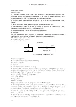
b) Test block diagram and meters
Instrument / equipment:
N type calibration kit(recommended model: 31101A)
N type calibration kit(recommended model: Agilent 85055A)
c) Test steps
1) Turn on the instrument for 30min warm-up.
2) Open the cable test window of the tested device by pressing the [Cable] hard key or pressing
the [Measurement] hard key and setting the instrument menu. Click this window, and the cable
test menu will pop up in the right side. Set it as follows:
Frequency setting: center frequency: 501MHz
SWR
port
Calibration kit
Fig. 7-14 Connection Diagram of SWR Measurement Range
Test
4992A
Rradio Test Set
Summary of Contents for 4992A
Page 1: ...I 4992A Radio Test Set User Manual China Electronics Technology Instruments Co Ltd...
Page 2: ......
Page 5: ......
Page 6: ......
Page 7: ......
Page 23: ...Article I Handling Instructions 11 Article I Handling Instructions...
Page 93: ...81 Article II Technical Specifications...
Page 132: ...Article III Maintenance Instructions 120 Article III Maintenance Instructions...


