Chapter IV Operation Guidance
43
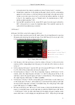
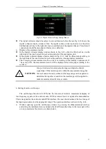
4-19 is generally applied in DTF measurement for fault point status measurement of connecting
cables of the base station, etc.
Fig. 4-19 Schematic Diagram of Connection of DTF Measurement
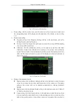
Window opening: open the cable test window by pressing the [Cable] hard key or
pressing the [Measurement] hard key and setting the instrument menu. Press the [Full
Screen] hard key in the lower part of the screen to maximize the window, as shown in Fig.
4-20.
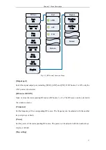
Fig. 4-20 DTFMeasurement Window
Menu calling: click the touch screen, select the cable test as the current active window, and
the corresponding menu will be displayed in the right side of the window, as shown in Fig.
4-20.
Measurement setting:
Frequency setting: click the [Frequency Setting] soft key in the right menu, and set the
starting frequency and stop frequency.
Setting of test type: click the [Test Type] soft key in the right menu and select the test
type [DTF] (fault point positioning measurement).
DTF test setting:
Setting of cable type: click [DTF Test]
→
[Cable Type] in the right menu and select
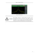
the cable type. 4992A is provided with a series of commonly used cable models to
be called by the user, as shown in Fig. 4-21. Select the corresponding cable mode
with the touch screen, knob, [
↑
] or [
↓
], and click the [Select] soft key or press the
[OK] hard key. Thus the cable model is called. In this case, the speed factor, cable
loss and other parameters can be matched automatically according to the selected
cable model.
Setting of relative speed: click the [DTF Test] soft key in the right menu of the
window and set the relative speed, i.e. speed factor of the cable (the speed factor
refers to the electromagnetic wave transmission speed in the cable and the speed of
light, i.e. 0-1).
Setting of cable loss: refer to the signal loss within the unit length.
Fault point
Antenna
Summary of Contents for 4992A
Page 1: ...I 4992A Radio Test Set User Manual China Electronics Technology Instruments Co Ltd...
Page 2: ......
Page 5: ......
Page 6: ......
Page 7: ......
Page 23: ...Article I Handling Instructions 11 Article I Handling Instructions...
Page 93: ...81 Article II Technical Specifications...
Page 132: ...Article III Maintenance Instructions 120 Article III Maintenance Instructions...

