5.2 Intake Pipe, Cylinder Head and Cylinder Body
05-61
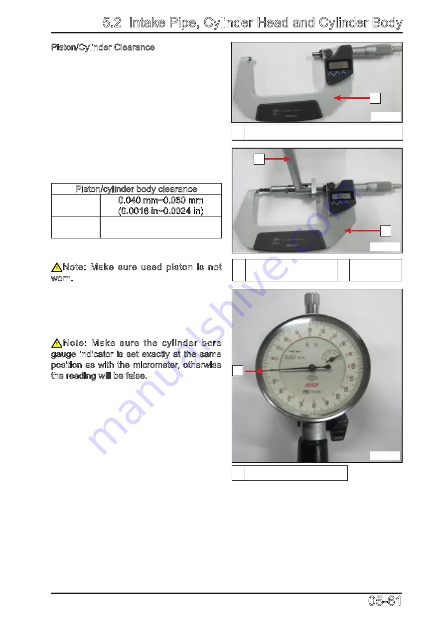
1 Micrometer Set to the Piston Dimension
1 Use Micrometer to
Adjust the Dial gauge 2 Dial Gauge
1 Indicator Set to 0 (zero)
056101
056103
056102
Piston/Cylinder Clearance
Adjust and lock micrometer to the piston
dimension.
With the micrometer set to the dimension,
adjust a cylinder bore gauge to the
micrometer dimension and set the indicator
to 0 (zero).
Position the dial bore gauge 20mm (0.787
in) above cylinder base, measuring
perpendicularly (90°) to piston pin axis.
Read the measurement on the cylinder
bore gauge. The result is the exact piston/
cylinder wall clearance.
Piston/cylinder body clearance
New
0.040 mm~0.060 mm
(0.0016 in~0.0024 in)
Service
limit
0.100 mm (0.0040 in)
Note: Make sure used piston is not
worn.
If clearance exceeds specified tolerance,
replace piston with a new one and
measure piston/cylinder clearance again.
Note: Make sure the cylinder bore
gauge indicator is set exactly at the same
position as with the micrometer, otherwise
the reading will be false.
2
1
1
1
Summary of Contents for CF1000ATR 2018
Page 1: ...CFMOTO SERVICE MANUAL CF1000AU CF1000ATR CFORCE 1000 ...
Page 81: ...CFMOTO 05 6 5 1 4 EIN Location EIN Location Engine left side Engine right side 050601 050602 ...
Page 351: ...06 Vehicle chassis 06 41 6 7 3 Front and rear CV shaft disassemble view 064101 064102 ...
Page 363: ...Appendix A ...
Page 364: ...Appendix B ...
Page 365: ...Appendix C ...


