5.3 Crankcase, Crankshaft and Gears
05-91
059102
059101
5.3.11 Shim Adjustment Procedure
When crankcase and/or drive pinion gear
and/or ring gear and/or bearing carrier are
replaced, the shim must be adjusted.
Warning: Both gear backlash and tooth
contact should be in specification.
Bevel Gear Clearance
Install the drive and driven bevel gear on
the crankcase. Set the gasket and close
the case . Then lock the case with several
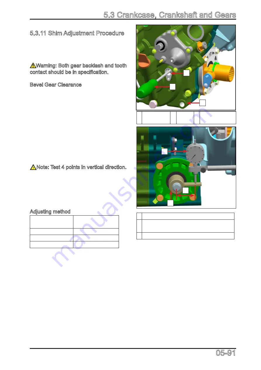
bolts. Use a screw driver to go through the
sealing cap mounting hole and insert into
drive bevel bearing seat hole. Lock the
driven bevel gear.
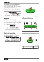
Install bevel gear clearance measuring tool
(0JWA-062000-922-001) and dial gauge.
Turn the drive and driven bevel gear to
measure the clearance.
Note: Test 4 points in vertical direction.
If side clearance is not in standard, please
adjust the thickness of adjusting shim and
test the clearance again and again until
the clearance is up to standard. Bevel gear
clearance: 0.1mm~0.2mm
Adjusting method
Measure
clearance
Adjusting shim
thickness
<0.1mm
Get thicker
0.1mm~0.2mm
OK
>0.2mm
Get thinner
1 Crankcase
LH
2 Screw
Driver 3
Sealing Cap
Mounting Hole
1 46mm (1.81in)
2 Gear Clearance Measuring Tool (P/N:
0JWA-062000-922-001)
3 Dial Gauge
3
1
2
3
2
1
Summary of Contents for CF1000ATR 2018
Page 1: ...CFMOTO SERVICE MANUAL CF1000AU CF1000ATR CFORCE 1000 ...
Page 81: ...CFMOTO 05 6 5 1 4 EIN Location EIN Location Engine left side Engine right side 050601 050602 ...
Page 351: ...06 Vehicle chassis 06 41 6 7 3 Front and rear CV shaft disassemble view 064101 064102 ...
Page 363: ...Appendix A ...
Page 364: ...Appendix B ...
Page 365: ...Appendix C ...


