CFMOTO
01-14
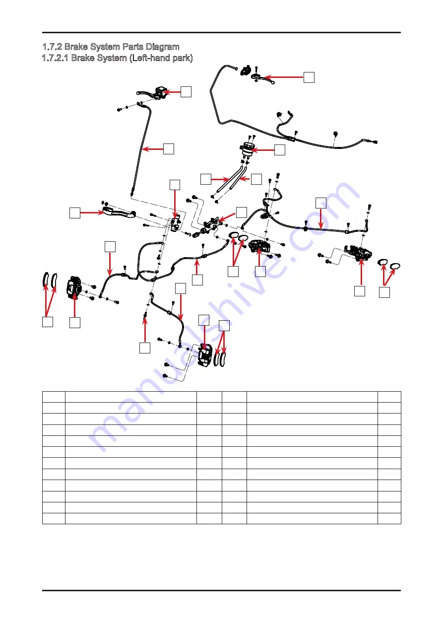
1.7.2 Brake System Parts Diagram
No.
Name
Qty No.
Name
Qty
1 Parking brake lever
1
12 Front Brake Hose, LH
1
2 Fluid Reservoir Assy
1
13 Front Brake Caliper, LH
1
3 Fluid Reservoir Hose 2
1
14 Front Brake Pad
2
4 Fluid Reservoir Hose 1
1
15 Hydraulic Induction Switch
1
5 Master Cylinder Assy
1
16 Front Brake Caliper, RH
1
6 Rear Brake Fluid Hose
1
17 Front Brake Pad Assy
2
7 Rear Brake Pad
2
18 Front Brake Hose, RH
1
8 Rear Brake Caliper, LH
1
19 Footrest Assy
1
9 Rear Brake Caliper, RH
4
20 Hydraulic Distribution Valve
1
10 Rear Brake Pad
2
21 Hand Brake Fluid Hose
1
11 Front Brake Fluid Hose
1
22 Hand Brake Pump Assy
1
011401
1.7.2.1 Brake System (Left-hand park)
7
8
6
9
10
11
12
15
13 14
16
17
18
19
21
20
4
3
2
5
1
22
Summary of Contents for CF1000ATR 2018
Page 1: ...CFMOTO SERVICE MANUAL CF1000AU CF1000ATR CFORCE 1000 ...
Page 81: ...CFMOTO 05 6 5 1 4 EIN Location EIN Location Engine left side Engine right side 050601 050602 ...
Page 351: ...06 Vehicle chassis 06 41 6 7 3 Front and rear CV shaft disassemble view 064101 064102 ...
Page 363: ...Appendix A ...
Page 364: ...Appendix B ...
Page 365: ...Appendix C ...


