5.4 CVT drive
05-119
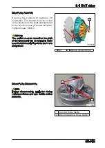
Drive Pulley Assembly
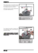
Reverse the removal procedures for
installation. The washer must be locked
in the position on the shaft and tightened
to the specific torque (Counterclockwise).
Tighten torque: 180N·m.
Warning
The washer must be locked on the shaft
or the drive pulley will be damaged. Make
sure the balance aligning marks are in one
straight line.
Driven Pulley Disassembly
Note:
Before disassembly, mark the spring
installation holes and cam feet to sliders
positions.
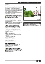
1 Cam and Slider Marks
2 Spring Installation Holes Marks
0511902
2
1
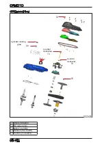
1 Nut
2 Balance Aligning Mark
0511901
1
2
Summary of Contents for CF1000ATR 2018
Page 1: ...CFMOTO SERVICE MANUAL CF1000AU CF1000ATR CFORCE 1000 ...
Page 81: ...CFMOTO 05 6 5 1 4 EIN Location EIN Location Engine left side Engine right side 050601 050602 ...
Page 351: ...06 Vehicle chassis 06 41 6 7 3 Front and rear CV shaft disassemble view 064101 064102 ...
Page 363: ...Appendix A ...
Page 364: ...Appendix B ...
Page 365: ...Appendix C ...

