05-185
5.8 Cooling System
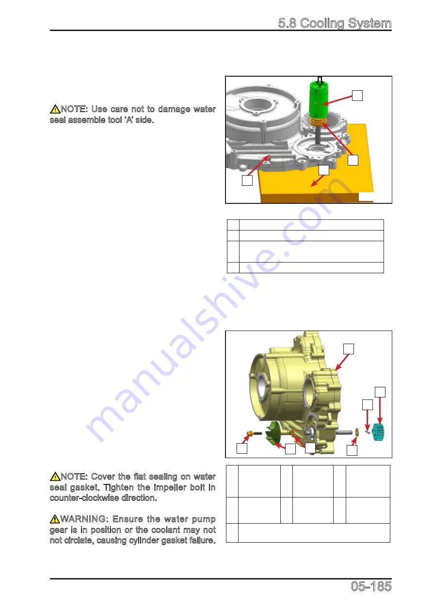
1 Left crankcase cover
2 Water pump shaft and water seal
3 Water seal pressor
(P/N:0JWA-081000-922-002)
4 Support plate(With hole)
1
Left
crankcase
cover
4
Water
seal
washer
6 Cross
Shaft
3 Impeller
5 Washer
7 Water
pump gear
2 Bolt (Counterclockwise)
0518502
0518501
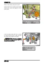
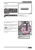
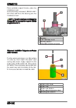
Use the water seal pressor ‘B’ side to
press the assembly into the Mag-side
crankcase cover in the direction as shown
in picture 0518501.
NOTE: Use care not to damage water
seal assemble tool ‘A’ side.
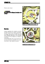
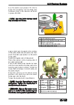
Apply a light coat of sealant on the surface
of the pump shaft end and water seal, then
place the water seal washer on the water
pump shaft.
Install the impeller and LH thread bolt.
Place the washer on the bearing side of
the water pump shaft.
Press on the water pump impeller by hand
until the cross shaft hole shows above the
bearing and washer surface. Install the
cross shaft and align it so both sides are
the same length.
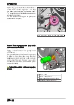
Align the groove of the water pump
gearand cross shaft, then push the water
pump gear onto the shaft.
Torque the impeller bolt to specification.
NOTE: Cover the flat sealing on water
seal gasket. Tighten the impeller bolt in
counter-clockwise direction.
WARNING: Ensure the water pump
gear is in position or the coolant may not
not circlate, causing cylinder gasket failure.
1
5
4
3
2
7
6
1
4
3
2
Summary of Contents for CF1000ATR 2018
Page 1: ...CFMOTO SERVICE MANUAL CF1000AU CF1000ATR CFORCE 1000 ...
Page 81: ...CFMOTO 05 6 5 1 4 EIN Location EIN Location Engine left side Engine right side 050601 050602 ...
Page 351: ...06 Vehicle chassis 06 41 6 7 3 Front and rear CV shaft disassemble view 064101 064102 ...
Page 363: ...Appendix A ...
Page 364: ...Appendix B ...
Page 365: ...Appendix C ...

