5.9 Electrical System
05-189
5.9.1 Charging System
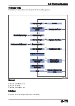
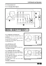
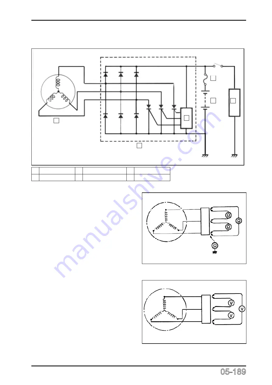
5.9.1.1 Charging Wire Diagram
0518901
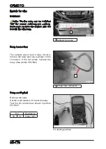
5.9.1.2 Magneto Coil Resistance
● Measure 3-phase magneto stator coil
resistance.
● If resistance is out of specification,
replace with a new stator coil.
●
Check for the insulation between stator
coil and stator core.
Turn multimeter to 1×10Ω
Magneto Coil Resistance:
0.5Ω~1.5Ω (Yellow-Yellow)
Resistance between Stator Coil and Core:
∞Ω (Yellow- Ground)
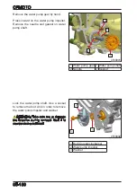
5.9.1.3 Magneto with Non-loaded
● Start the engine and run it at 5000r/min.
Use multimeter to measure the voltage
between 3 output lines.
● If the reading is below the specification,
replace with a new magneto.
Turn Multimeter to V(AC)
Voltage between output lines when MAG
Non-loaded:
>50V(AC) at 5000r/min
0518902
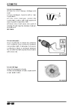
Measure resistance
Measure voltage
0518903
1
2
3
4
5
6
1 Magneto
3 Voltage regulator 5 Battery
2 Regulator
4 Fuse
6 Load
Summary of Contents for CF1000ATR 2018
Page 1: ...CFMOTO SERVICE MANUAL CF1000AU CF1000ATR CFORCE 1000 ...
Page 81: ...CFMOTO 05 6 5 1 4 EIN Location EIN Location Engine left side Engine right side 050601 050602 ...
Page 351: ...06 Vehicle chassis 06 41 6 7 3 Front and rear CV shaft disassemble view 064101 064102 ...
Page 363: ...Appendix A ...
Page 364: ...Appendix B ...
Page 365: ...Appendix C ...

