5.9 Electrical System
05-199
5.9.4 EFI Components and Function
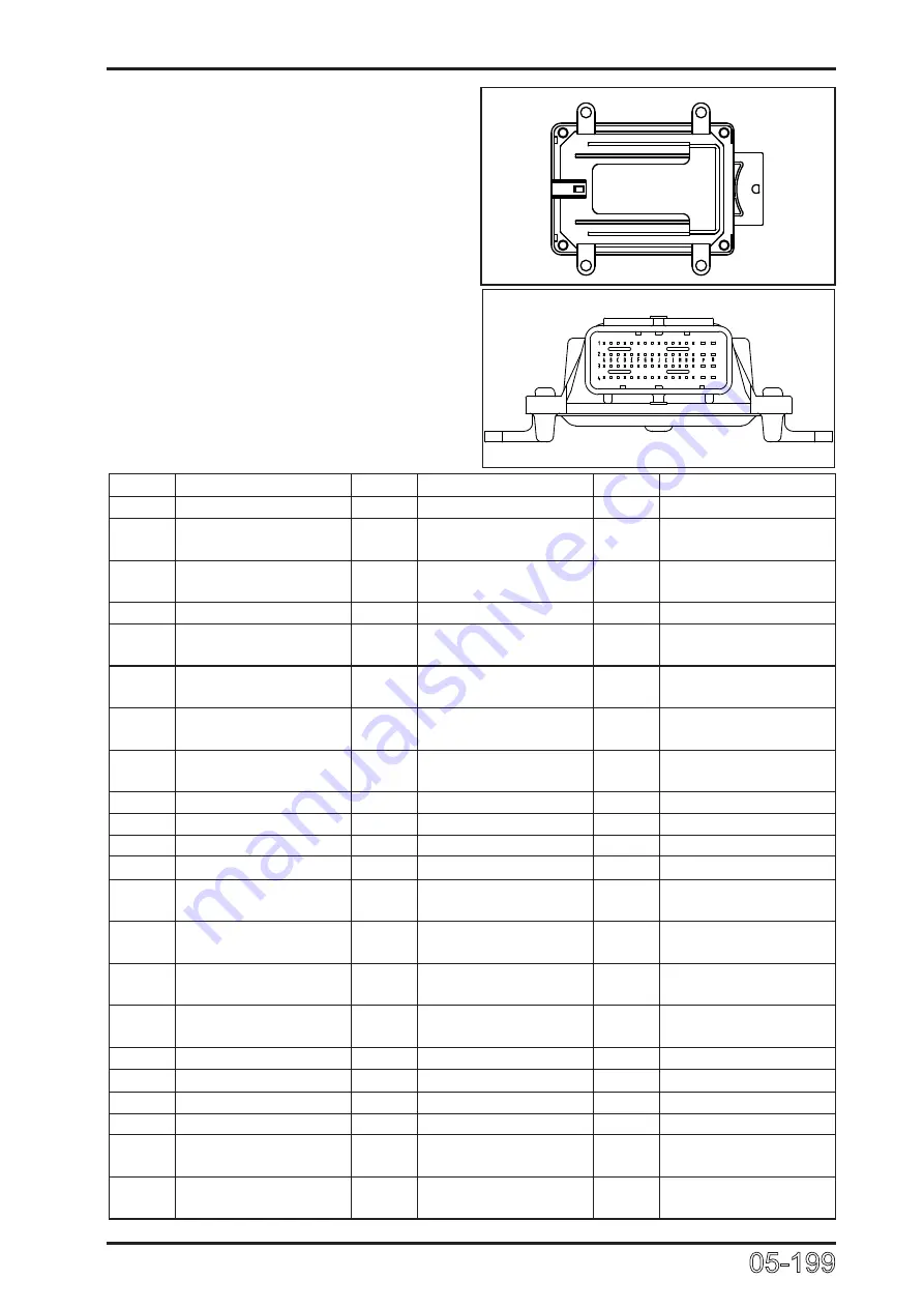
5.9.4.1 ECU
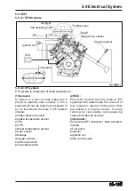
Electronic Control Unit, the brain of EFI
system, which determines the amount
of fuel injection, ignition timing and other
parameters a engine needs to keep
running by calculating and analyzing
values provided by sensors.
ECU
0519901
No.
Function
No.
Function
No.
Function
1(Q1) /
23(O2) Auxiliary relay
45(F3) Oxygen sensor 1
2(P1) Oxygen sensor heat 1 24(N2) /
46(E3) Engine RPM sensor B
side
3(Q2) Ignition coil 1
25(M2) Intake temp. sensor
47(D3) Engine RPM sensor A
side
4(P2) Oxygen sensor heat 2 26(L2) TPS
48(C3) Power ground
5(Q3) Ignition coil ground
27(K2)
Clutch switch
49(B3) Injector 2 (Second
cylinder)
6(P3) /
28(J2) /
50(A3) I n j e c t o r 1 ( F i r s t
cylinder)
7(Q4) Ignition coil 2
29(H2) Oxygen sensor 2
51(O4) Non continuous power
supply
8(P4) Non continuous power
supply
30(G2) /
52(N4) /
9(O1) Engine RPM output
31(F2) /
53(M4) /
10(N1) /
32(E2) Main relay
54(L4) Sensor ground 3
11(M1) Over-roll switch
33(D2) /
55(K4)
/
12(L1) /
34(C2) /
56(J4) /
13(K1)
Mode switch
35(B2) Stepping motor phase
C
57(H4) /
14(J1) Neutral switch
36(A2) Stepping motor phase
D
58(G4) /
15(H1)
K-line
37(O3) Canister magnetic
valve
59(F4) I n t a k e p r e s s u r e
sensor
16(G1) Continuous power
supply
38(N3) /
60(E4) Fuel pump relay
17(F1) Ignition switch
39(M3) Sensor ground 1
61(D4) /
18(E1) 5V power 2
40(L3) Sensor ground 2
62(C4) Fan relay
19(D1) 5V power 1
41(K3)
Water temp. sensor
63(B4) /
20(C1) MIL
42(J3) Side stand switch
64(A4) /
21(B1) Stepping motor phase
B
43(H3) Signal ground
22(A1) Stepping motor phase
A
44(G3) /
ECU pin position
0519902
Summary of Contents for CF1000ATR 2018
Page 1: ...CFMOTO SERVICE MANUAL CF1000AU CF1000ATR CFORCE 1000 ...
Page 81: ...CFMOTO 05 6 5 1 4 EIN Location EIN Location Engine left side Engine right side 050601 050602 ...
Page 351: ...06 Vehicle chassis 06 41 6 7 3 Front and rear CV shaft disassemble view 064101 064102 ...
Page 363: ...Appendix A ...
Page 364: ...Appendix B ...
Page 365: ...Appendix C ...

