background image

CFMOTO

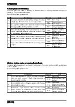
05-216

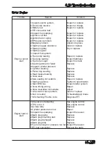
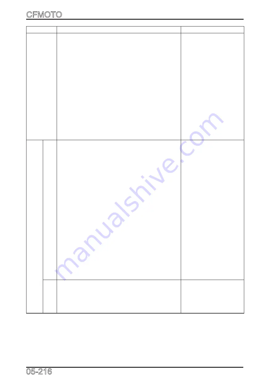
Trouble 

Reason 

Solution

Engine 

overheat

1.Coolant level too low

2.Cooling system has bubble

3.Water temp sensor problem

4.Thermostat cannot open

5.See leaking hole to see leaking

6.Inspect the water hose and clamp

●Water pipe cracked or aging

●Clamp loose

7.Water pump impeller broken

8.Water pump gasket leaking

9.Cylinder head or body gasket leaking

10. Water pump drain bolt leaking

11. Water pump gear wearing

12. Water pump shaft jammed

Refill

Drain the air and refill

Replace

Replace

Replace the water seal

Replace

Tight

Replace

Tight or replace

Replace

Tight or replace the 

gasket

Replace

Replace the parts

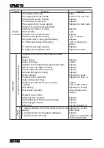
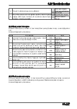
Lubrication

Oil pressure low or no pressure

1.Inspect the oil level to see case or oil seal 

leaking.

●Case broken

●Case bolt loose

●Sealing ring/O-ring/Sealing gasket damaged

●Piston ring broken(Blue smoke)

●Piston ring broken(Pressure low)

●Oil seal damaged or aging

2.Filter plugged

3.Inspect the oil drain bolt

●Case bottom bolt loose

●Crankcase drain bolt loose or without

   washer

4.Oil leaking

5.Oil strainer jammed 

6.Inspect the oil pump

●Oil pump rotor wearing

●Oil leaking or air income jam the pump

●Oil pump gear broken

●Wrong oil

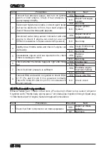
Replace

Tighten

Replace

Replace

Replace

Replace

Replace the seals

Replace the filter, oil

Tighten

Tight or with washer

Replace the oil seal

Clean, Replace the 

strainer

Replace

Replace

Replace

Use recommend oil

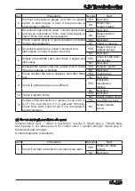
Oil becoming


white

1. Leaking indicate the oil and water mixed up and 

leaking

2. Cylinder head or body gasket damaged

3. Cylinder head bolt loose

Replace the oil and 

water seals

Replace

Tighten or replace the oil 

and damaged parts

Summary of Contents for CF1000ATR 2018

Page 1: ...CFMOTO SERVICE MANUAL CF1000AU CF1000ATR CFORCE 1000 ...

Page 2: ...CFMOTO Edition No 20180817 Edition item CF1000AU 9AY0 WX 01 1 SM 20180817 Website www cfmoto com 1 ...

Page 3: ...introduces assemble and disassemble procedures of body covering parts Chapter 3 mainly introduces checking adjustment methods and how to do vehicle maintenance Chapter 4 mainly introduces how to remove the parts at alongside of the engine Chapter 5 mainly introduces how to remove check and maintain the engine parts Chapter 6 mainly introduces the information of the vehicle chassis Chapter 7 mainly...

Page 4: ... potential hazard that may cause serious injuries or death Warning The Warning alert and icon indicates a potential hazard that may cause light or medium injury Caution The Caution alert and icon indicates a potential hazard that requires you to pay attention NOTE or NOTICE A note or notice alerts to important information or instructions Please pay attention Danger Warning and Caution cannot inclu...

Page 5: ...ot drink or spill it on skin eyes or clothes If you spill coolant on skin wash with soap and water If you spill coolant on eyes flush with water and seek prompt mediacal attention If coolant is swallowed induce vomiting and ask a doctor for medical care Keep coolant out of reach of children and away from pets 6 Gasoline is highly flammable Keep gasoline away from sparks Vaporized gasoline is also ...

Page 6: ...ip after assembling to make sure it has been installed into the slot 15 After assembling check that all the tightened parts are properly tightened and can move smoothly 16 Brake fluid and coolant may damage painting plastic and rubber parts Flush with water if splashed on these parts 17 Install oil seals with the side of manufacturer s mark outward Do not fold or scratch the oil seal lip Apply gre...

Page 7: ...de 0 300km Do not operate continously at more than 50 throttle position Cool down the engine for 5 10 minutes after every one hour of operation Avoid sudden acceleration Vary the throttle position slowly and smoothly 300km 600km Avoid long time running at more than 75 throttle position Do not open throttle completely during this period NOTE 1 Maintain and repair with regular procedures during brea...

Page 8: ...cification Front wheel 27 9 00 12 51K 27 9 00R14 60L Rear wheel 27 11 00 12 57K 27 11 00R14 66L Min ground clearance 285mm Min turning radius 7800mm Engine Starting Electric Type V twin cylinder 4 stroke liquid cooled 8 valves SOHC Valves Timing chain drive Bore Stroke 91mm 74mm Compression ratio 10 6 1 Lubrication Compressed splashing Oil pump Rotor Oil filter Paper filter Engine oil type SAE15W ...

Page 9: ...Gear order Manual H L N R P CVT ratio 0 7 2 88 Gear shift ratio H gear L gear R gear Final 1 333 Secondary 1 952 Single 1 143 2 529 2 231 Total 2 975 6 585 5 807 Ratio of drive axle Front 33 9 3 667 Rear 33 9 3 667 Output type Front Rear shaft drive Rotation of engine output clockwise rear view when tranmission in forward Steering Turn angle inner 32 5 outer 24 2 Brakes Front Hydraulic Disc Rear H...

Page 10: ...engine RPM is 1300r min and oil temperature is 90 C oil pressure should be 100kPa 400kPa usually is 200kPa When engine RPM is 6000r min and oil temperature is 90 C oil pressure should be 350kPa 700kPa usually is 580kPa Intake system See 05 Engine Cooling system Item Standard Remark Coolant capacity Total About 4000mL Reservoir 200mL 380mL Density 50 Opening pressure 108 kPa 1 1kgf cm2 Thermostat O...

Page 11: ... without load cold engine 50V AC 5000r min Output power 350W 5000r min 460W 5000r min Stable voltage 13 5V 15 0V Peak voltage of pick up 3V 200 r min Regulator type 3 phase supply power circuit Battery Capacity 12Vdc 30Ah Voltage between terminals Fully recharged 14 4V Not fully recharged 11 8V Recharging current time Standard 2 7A 5h 10h Quick 12A 1h Ignition equipment Item Standard Ignition cont...

Page 12: ... Engine 1 5 Tighten torque NOTE Cover the screw with anti rust grease before installation Special torque list refers to frame chapters Item Standard Fuse Main 30A Secondary 40A 1 EPS 15A 3 10A 2 Light and bulb Headlight 12V 12W 14W LED Brake light Tail light 12V 4 8W 12LED Front turning light 12V 1 2W 7LED Rear turning light LED Indicators LED Rear license light 12V W5W BULB ...

Page 13: ...le GB6187 M10 1 25 3 50 60 14 Mounting nut rear axle GB6187 M10 1 25 3 60 70 15 Screw rear drive shaft GB T70 1 M10 1 25 25 4 40 50 16 Nut steering lever ball pin 9010 100002 4 40 50 17 Bolt handlebar cover GB5789 M8 60 4 30 40 18 Bolt front brake caliper GB5789 M10 1 25 20 4 40 50 19 Bolt front brake disc 9010 080003 16 30 35 20 Bolt rear brake caliper GB5789 M10 1 25 20 4 40 50 21 Banjo bolt 702...

Page 14: ...e cable connecting point Throttle pedal moving point Brake pedal moving point Rocker arm moving point Steering column inner face Seat lock moving point Shifting mechanism moving point Multifunction lithium grease Cable bearing and other moving parts lubrication Parts Item Grease Steering shaft ball sleeve Lubrication Lithium grease for auto GB T5671 Rear wheel hub Shock absorber knuckle bearing Th...

Page 15: ...ime running light control unit connector A B 16 Power output connector 5 Connector front axle motor 11 RH handlebar connector 6 Connector ignition swich lock 12 Fan motor connector A B 011102 1 2 4 WD Relay 4 Fan Motor Relay 7 Battery 2 4 4WD Lock Relay 5 DRL Relay 8 Diagnose Connector 3 Fuel Pump Relay 6 Main Relay 9 ECU Note Remove the body covering parts before inspection Removal procedures ref...

Page 16: ... 3 Starter Motor Note Remove the body covering parts before inspection Removal procedures refer to Chapter 2 011201 1 Idle Stepping Motor 2 TPS 3 Injector Note Remove the seat assembly before inspection of those part Removal procedures refer to Chapter 2 1 3 2 011202 2 1 3 5 4 ...

Page 17: ...Note Remove the right panel before working on the parts mentioned above Removal procedures refer to Chapter 2 011301 Note Remove the body covering parts before inspection Removal procedures refer to Chapter 2 011302 1 Connector Right Turn 3 License Light Connector 2 Connector Left Turn 4 Tailer Power Connector 1 4 3 2 Driving direction 1 2 4 3 ...

Page 18: ...ion Switch 1 5 Master Cylinder Assy 1 16 Front Brake Caliper RH 1 6 Rear Brake Fluid Hose 1 17 Front Brake Pad Assy 2 7 Rear Brake Pad 2 18 Front Brake Hose RH 1 8 Rear Brake Caliper LH 1 19 Footrest Assy 1 9 Rear Brake Caliper RH 4 20 Hydraulic Distribution Valve 1 10 Rear Brake Pad 2 21 Hand Brake Fluid Hose 1 11 Front Brake Fluid Hose 1 22 Hand Brake Pump Assy 1 011401 1 7 2 1 Brake System Left...

Page 19: ... 1 5 Master Cylinder Assy 1 16 Front Brake Caliper RH 1 6 Rear Brake Fluid Hose 1 17 Front Brake Pad Assy 2 7 Rear Brake Pad 2 18 Front Brake Hose RH 1 8 Rear Brake Caliper LH 1 19 Footrest Assy 1 9 Rear Brake Caliper RH 4 20 Hydraulic Distribution Valve 1 10 Rear Brake Pad 2 21 Hand Brake Fluid Hose 1 11 Front Brake Fluid Hose 1 22 Hand Brake Pump Assy 1 011501 1 7 2 2 Brake System EU 167 Left ha...

Page 20: ...Name Qty 1 Parking Lever Assy 1 2 Parking Brake Cable 1 3 Rear View Mirror Seat Assy 1 Remark Others please refer to chart 011401 Exclude 21 and 22 011601 3 2 1 1 7 2 3 Brake System Right hand park 1 Front Brake Fluid Hose 3 Master Cylinder Assy 2 Shifting Locking Cable 4 Rear Brake Fluid Hose 1 4 3 2 011602 ...

Page 21: ...e I Idle 2 Coolant Filler Connecting Pipe 5 Flow Hose Reservoir 8 Coolant Reservoir Assy 3 Coolant Outlet Hose 6 Hose Coolant Reservoir Note Remove the body covering parts before inspection Removal procedures refer to Chapter 2 1 7 3 Cooling System Parts Diagram 011701 1 5 4 3 2 8 7 6 ...

Page 22: ...over Front Deco Plate Front Ventilate Cover Headlight Cover 2 5 1 Front Lower Panel 2 13 2 5 2 Front Licence Plate 2 13 2 5 3 Front Bumper Block 2 13 2 5 4 Front Bumper 2 14 2 5 5 Front Deco Cover LH RH 2 14 2 5 6 Headlight Cover LH RH 2 15 2 5 7 Front Deco Plate 2 15 2 5 8 Front Ventilate Cover 2 15 2 5 9 Headlight Plate 2 16 2 6 Front Fender LH RH Front Upper Inner fender LH RH Front Fender Engi...

Page 23: ...nd installation procedures Also the rack seat backrest removal and installation instructions Follow the drawings to arrange the cables pipes and wirings to the correct position 2 2 Tighten Torque M8 bolt 20 2 0 Torque N m kgf m M6 bolt 10 1 0 Torque N m kgf m M5 bolt 5 0 5 Torque N m kgf m Screw 4 0 4 Torque N m kgf m ...

Page 24: ...t Seat Removal Remove the rear seat See 2 3 1 Lift the front seat hook 1 Lift the rear part of front seat and pull seat out Installation Reverse the removal procedures for installation Make sure the seat is totally locked after it is assembled 2 3 3 Air Filter Cover Assy Removal Remove the front seat See 2 3 2 Loosen three rubber sleeves at each side 1 Lift up the rear part to loosen the rubber sl...

Page 25: ...2 3 5 Air Filter Cover RH Removal Remove air filter cover See 2 3 3 Remove three self tapping scews 1 Remove plastic clip 2 Remove air filter right cover 3 Installation Reverse the removal procedures for installation 2 3 6 Air Filter Upper Cover Removal Remove air filter cover See 2 3 3 Remove six self tapping screws 1 Remove two plastic clips 2 Remove air filter upper cover 3 Installation Reverse...

Page 26: ...er 2 Installation Reverse the removal procedures for installation 2 3 8 Left Side Cover Removal Remove shifting deo cover See 2 3 7 Loosen six rubber sleeves 1 Loosen two plastic clips 2 Remove left side cover 3 Installation Reverse the removal procedures for installation 020501 020502 020503 2 1 020504 3 2 4 1 1 2 3 2 1 1 2 3 2 3 7 2 Gearshift Deco Cover Russian status Removal Remove air filter c...

Page 27: ...ide cover See 2 3 8 Remove right side cover See 2 3 9 Remove two screws 1 Remove diagnose connector 2 Remove two screws 3 Remove the fluid reservoir 4 Remove four M6 bolts 5 Remove seat heat insulator 6 Installation Reverse the removal procedures for installation 2 3 11 Rear Seat Bracket Removal Remove the front seat See 2 3 2 Remove five M6 bolts 1 Remove rear seat bracket 2 Installation Reverse ...

Page 28: ... removal procedures for installation Right Cover Removal Remove four M6 bolts 1 Lift up to remove the cover 2 Installation Reverse the removal procedures for installation Left Cover Removal Installation See right cover instructions 2 4 2 Front Rack Removal Remove front rack cover See 2 4 1 Remove four M8 bolt 1 Remove two M6 bolts 2 from fender One piece on each side See picture 020801 Remove fron...

Page 29: ...k cover 2 Installation Reverse the removal procedures for installation 2 4 4 Rear Rack Removal Remove the bracket cover See 2 4 3 Remove four M8 bolts 1 Remove two M6 bolts 2 from fender One piece on each side See 020901 Remove rear rack 3 Installation Reverse the removal procedures for installation 1 3 2 1 1 1 2 ...

Page 30: ...ndle bar cover 2 Installation Reverse the removal procedures for installation 2 4 6 Hand Guard LH RH Hand Guard RH Removal Remove one M6 bolts 1 Remove one M8 bolts 2 Remove right hand guard Installation Reverse the removal procedures for installation Hand Guard LH Removal installation See right guard instructions 1 2 2 2 3 4 1 8 ...

Page 31: ...l Remove two screws 6 See pic 021001 Loose five plastic clip 7 See pic 021001 Remove the deco cover 8 See pic 020903 Installation Reverse the removal procedures for installation Handlebar Deco Cover LH Removal installation See right cover instructions 2 4 7 Dashboard Cover Assy Removal Remove air filter cover See 2 3 3 Loose two rubber sleeves 1 Loose two plastic clips 2 Disconnect dashboard conne...

Page 32: ...Remove the ignition switch 2 Loose three plastic clips 3 Remove right dashboard cover 4 Installation Reverse the removal procedures for installation 2 4 9 Dashboard Cover LH Removal Remove the dashboard cover See 2 4 7 Remove two screws 1 from dashboard cover Loose three plastic clips 2 Remove left dashboard cover 3 Installation Reverse the removal procedures for installation 1 4 3 2 3 1 3 2 ...

Page 33: ... for installation 2 4 11 Dashboard Cover Removal Remove dashboard lower cover See 2 4 10 Remove five screws 4 See picture 021203 Loose four plastic clips 5 See picture 021203 Remove the dashboard cover 6 See picture 021203 Installation Reverse the removal procedures for installation 2 4 12 Front Dashboard Cover Removal Remove dashboard lower cover See 2 4 10 Remove five screws 4 Loose four plastic...

Page 34: ...r panel 2 Installation Reverse the removal procedures for installation 2 5 2 Front Licence Plate Removal Remove four M6 bolt 1 Remove front licence plate 2 Installation Reverse the removal procedures for installation 2 5 3 Front Bumper Block RH Remove front license plate See 2 5 2 Remove one M6 bolt 1 Remove front right bumper block Installation Reverse the removal procedures for installation Fron...

Page 35: ... Removal See left bumper cover instructions Front Bumper Cover LH US Removal Remove one M6 bolt 1 Remove front bumper left cover 2 Remove the reflector 3 Installation Reverse the removal procedures for installation Front Bumper Cover RH Removal See left bumper cover instructions 2 5 5 Front Deco Cover RH Removal Remove front license deco plate See 2 5 2 Remove three screws 1 Remove one screw 2 Loo...

Page 36: ...ion See right headlight cover instructions 2 5 7 Front Deco Plate Removal Loosen four rubber sleeve 1 Loosen two plastic clip 2 Loosen plastic clip 3 Remove the deco plate 4 Installation Reverse the removal procedures for installation 2 5 8 Front Vent Cover LH Removal Loosen three rubber sleeve 1 Loosen one plastic clip 2 Remove front left vent cover 3 Installation Reverse the removal procedures f...

Page 37: ...e four screws 3 Two on each side See picture 021602 Remove two screws 4 one on each side Remove four screws 5 See picture 021601 Remove four M6 bolts 6 See picture 021601 Disconnect two headlight connectors 7 One for each side See picture 021603 Remove headlight panel 8 Remove eight screw 9 Four on each side See picture 021604 Remove headlight See picture 021604 Installation Reverse the removal pr...

Page 38: ... Fender 2 6 1 Front Flare Fender RH Removal Loosen six screws 1 Remove front right fender 2 Installation Reverse the removal procedures for installation Front Flare Fender LH Removal See right fender instructions 2 6 2 Front Inner Fender RH Removal Remove right headlight cover See 2 5 6 Remove six screws 1 Remove front right inner fender 2 Installation Reverse the removal procedures for installati...

Page 39: ... Remove four M6 bolts 1 Two on each side See picture 021801 021802 Remove one M6 bolt 2 See picture 021802 Remove two M6 bolts 3 See picture 021803 Loosen four plastic locking points 4 two on each side Loosen the screw to remove the power output 5 See picture 021804 Loosen the screw to remove the USB connector 6 See picture 021804 Remove the relay box 7 See picture 021803 Remove the front fender 8...

Page 40: ...dures for installation Side Cover Bracket Removal Remove three M6 bolt 1 Remove side cover bracket 2 Installation Reverse the removal procedures for installation 2 6 5 Rear Flare Fender RH Removal Remove five screws 1 Remove rear right widen fender 2 Installation Reverse the removal procedures for installation Rear Flare Fender LH Removal See right fender instructions 021901 021902 1 2 1 3 2 2 1 ...

Page 41: ...installation Footrest LH Removal installation It is same with right footrest 2 6 7 Rear License Plate Removal Remove two M6 bolts 1 Remove rear licence plate 2 Remove one screw 3 Disconnect rear license light Remove rear license light 4 Installation Reverse the removal procedures for installation 2 6 8 Tool Box Cover Removal Open the tool box cover 1 Remove the cottor pin 2 Remove the axle 3 Remov...

Page 42: ...ion 2 6 10 Rear Plate Removal Remove rear seat See 2 3 1 Remove rear cargo bracket See 2 4 4 Open tool box cover 1 Remove six screws 2 Remove two screws 3 Remove rear plate 4 Installation Reverse the removal procedures for installation 2 6 11 Tool Box Locker Bracket Removal Remove rear plate See 2 6 10 Remove four screws 1 Remove tool box locker bracket 2 Installation Reverse the removal procedure...

Page 43: ...verse the removal procedures for installation Reflector Removal Loose two M6 bolts 7 Remove rear reflector bracket 8 Loose two M6 nuts 9 Remove rear reflector 10 Installation Reverse the removal procedures for installation Right Taillight Removal Remove four screw 11 See picture 022203 Remove taillight 12 See picture 022203 Installation Reverse the removal procedures for installation Taillight Cov...

Page 44: ...ool box cover locker bracket See 2 6 11 Remove taillight plate LH RH See 2 6 12 Remove two M6 bolt 1 Remove four M6 bolt 2 2 on each side See picture 022302 Loose four plastic clips 3 2 on each side See picture 022302 Remove the tank cover 4 See picture 022303 Remove rear fender 5 Installation Reverse the removal procedures for installation 022302 3 2 1 5 ...

Page 45: ...M6 bolts 1 Remove front lower panel 2 Installation Reverse the removal procedures for installation 2 7 2 Middle Lower Plate Removal Remove five M6 bolts 1 Remove middle lower plate 2 Installation Reverse the removal procedures for installation 2 7 3 Rear Lower Plate Removal Remove four M6 bolts 1 Remove rear lower plate 2 Installation Reverse the removal procedures for installation 1 2 1 2 1 2 ...

Page 46: ...l installation See right suspension cover instructions 2 7 5 Rear Suspension Cover LH Removal Remove one M6 bolt 1 Remove rear left suspension cover 2 Installation Reverse the removal procedures for installation Rear Suspension Cover RH Removal installation See left suspension cover instructions 2 7 6 Pipe Plug Removal Remove rear lower plate See 2 7 3 Remove pipe plug 1 Installation Reverse the r...

Page 47: ...CFMOTO 02 26 1 2 8 Seat Belt EU 167 Removal Remove two bolts 1 Remove seat belt assy 2 Installation Reverse the removal procedures for installation 022601 2 ...

Page 48: ...ecautions DANGER Exhaust contains carbon monoxide and other poisonous components Do not run the engine in a enclosed area for long time The muffler and engine temperature is still high when the engine is just stopped It may cause burns when touched to skin Wear long sleeves and gloves if you have to perform maintenance when the engine is just stopped Gasoline is highly flammable No smoking or fire...

Page 49: ...ly A Adjust C Clean I Inspect L Lubricate R Replace 10h or 300km Every 25h or 750km Every 50h or 1500km Every 100h or 3000km or a year Every 200h or 6000km or 2 year Remark Engine Oil and oil filter R R Gear oil R I R Oil strainer I C I C Valve adjustment I A I A Engine sealing I I Engine suspension I I Air filter element C R Coolant I I R Radiator and cooling system I I Spark plug I R Fuel system...

Page 50: ... disc wear When the front and rear disc thickness is less than 4mm replace the disc Riding System Wheel Tire pressure Front 45kPa 0 45kgf cm 6 5PSI Rear 45kPa 0 45kgf cm 6 5PSI Tire cracks or damaged Tire groove depth and wear The groove depth should be deeper than 3mm Wheel nut and axle looseness Front wheel bearing movement Rear wheel bearing movement Shock absorber Pivot arm Connecting shock an...

Page 51: ...ry Connectors condition Wiring Connecting loose and damage Fuel system Fuel leaking Throttle lever Throttle lever clearance 3mm 5mm Cooling system Water level Leaking Item Period Standard Part Inspection Item Daily Half a year Yearly Lighting system Function Warning and 4WD locker Function Dashboard Function Muffler Loose or damage Muffler function Frame Loose or damaged Other Frame Components abn...

Page 52: ...dlebar slowly to check for interference If any portion of the steering jammed inspect the main cable or other cables for interference If the steering rod end position has not been inspected make sure it has no interference and the steering bearing is OK CAUTION Make sure the steering system is moving smoothly Failure of the steering system will cause an accident Front Brake Clearance of the front ...

Page 53: ...void chemical reaction Don t spill brake fluid on plastic or rubber parts as it could damage them Turn handlebar to left or right as necessary to keep the master cylinder level before the reservoir cap is removed Front Brake Disc Brake Pads Brake Pad Wear Inspect brake pads from the marked place Replace brake pads if they are worn to service limit groove Braking Pad service limit 1 5mm CAUTION Pad...

Page 54: ... avoid chemical reaction Don t spill brake fluid on plastic or rubber parts as it could damage them Brake Fluid Replacement Replace brake fluid every year Rear Brake Disc Rear Brake Pads Brake Pad Wear Inspect rear brake pads from the marked place Replace rear brake pads if they are worn to service limit groove Braking Pad service limit 1 5mm CAUTION Pads should be replaced as an assembly Brake Di...

Page 55: ...hten them if necessary If free play or looseness still remains inspect bearings A arm bushings ball joints pins and replace if necessary Front Wheel Toe in Position the vehicle on a level ground to measure the front wheel toe in Front A Rear B Toe in B A 4mm 10mm If the measurement is out of specification adjust the tie rod 1 and tighten locking nuts 2 CAUTION Drive the vehicle slowly after the ad...

Page 56: ...rability comfort or uneven wear to tires Tire and tire pressure Front wheel Rear wheel Tire 45kPa 0 45kgf cm 6 5PSI 45kPa 0 45kgf cm 6 5PSI Tire size 27 9 00 12 51K 27 11 00 12 57K Tire size 27 9 00R14 60L 27 11 00R14 66L Tire groove Replace tires when tire tread depth is worn to 3mm or less CAUTION When tread depth is worn to 3mm or less replace tires immediately Avoid sliding when driving 030901...

Page 57: ...que Front axle nut 220N m 250N m 22kgf m 25kgf m Rear axle nut 220N m 250N m 22kgf m 25kgf m 3 5 Suspension System Set the vehicle on a flat ground Press on the vehicle body several times at the position sshowed below If there is noise or movement inspect the shock absorber and check oil leaking Check that all the locking parts are not damaged or loose 031001 031002 1 ...

Page 58: ... 3 to adjust it Remove three M8 bolts 4 Remove shifting mechanism 5 See picture 031102 3 7 Fuel System Inspect Fuel System Condition Remove seat See 2 3 Check fuel lines for aging damage Replace fuel line if aging damage is found Inspect fuel tank breather hose and the hose of fuel evaporation control system if appliable for damages and bending Replace the hoses if any damage is found See picture ...

Page 59: ...rottle cable Speed Limiter Speed limiter is designed to adjust throttle lever travel so as to limit the max speed Inspect the max length of limiter screw threads Max limiter screw threads a 12mm Adjustment Loosen the locking nut 1 Use a cross screw driver to turn the limiter screw 2 clockwise or counter clockwise to adjust throttle lever travel CAUTION For beginners keep the adjuster screw turned ...

Page 60: ...eek medical attention If you swallow coolant immediately spit it out and gargle then seek medical attention Coolant must be kept out of reach of children and pets Coolant Level Coolant can decrease due to evaporation etc Inspect coolant level periodically CAUTION Coolant is anti rust and anti freezing Using tap water can corrode the engine and may crack the engine when it s freezing Always use spe...

Page 61: ...voir tank there may be air in the cooling system Purge the cooling system of air during the refill Coolant Leakage Inspect radiator hoses water pump and connections for leaks If any leaks are found repair the cooling system Inspect radiator hoses for aging damages and cracks Hoses ages over time due to special working conditions and may crack Bend a hose to inspect for cracks If any damage or crac...

Page 62: ...olant gauge for response If the indicator doesn t move when the engine is warm determine the cause and repair See picture 031501 3 10 Lighting Headlight Beam Adjustment Remove headlight protector In order to adjust headlight beam turn the screws 1 to adjust the headlight beam vertically and horizontally See picture 031502 O O O OP P P PC C C C 1 031501 031502 1 ...

Page 63: ...Selective Shock Absorber View D a m p i n g Force Knob for Restoring D a m p i n g Force Knob for Restoring Damping Force Knob for Compression Damping Force Knob for Compression Spring adjust nut Spring adjust nut 031601 ...

Page 64: ...creases when adjusting in the direction of Slow The resistance decreases when adjusting in the direction of Fast Rear Shock Absorber Adjustment According to load deviation adjust damping force knob for compression 1 and damping force knob for restoration 2 The resistance increases when adjusting in the direction of Slow The resistance decreases when adjusting in the direction of Fast 1 2 1 2 03170...

Page 65: ...CFMOTO 03 18 Adjusting retainer Adjusting retainer Front shock absorber Rear shock absorber 3 12 Shock Absorber Selection Front Rear Shock Absorber Shape Selection 031801 ...

Page 66: ...reload position 1 depends on the vehicle load Turn it clockwise to increase the spring preload See picture 031701 Rear shock absorber spring preload adjustment Use shock absorber adjusting tool Adjusting the retainer position 1 depends on the vehicle load Turn it clockwise to increase the spring preload See picture 031702 1 1 031901 031902 ...

Page 67: ...ries Do not damage the frame engine body bolts or cables Be careful when working Wrap the frame in appropriate areas where might it be scratched to avoid damage during engine removal and installation Use special containers to collect drained coolant engine oil and fuel when removing the engine Replace the coolant and oil as standard procedure after assembling the engine It is not necessary to remo...

Page 68: ...he clamp A10 1 Remove fuel vapor hose II 2 Remove the clamp A10 1 Remove fuel vapor hose I 2 Remove nuts 1 Remove canister 2 Reverse the removal procedures for installation Inspection Check canister for damage Replace if necessary Check fuel vapor hose for age or damage Replace if necessary 1 2 1 2 1 2 040201 040202 040203 ...

Page 69: ... Remove body covering parts See 02 body covering parts Remove four M6 bolt 1 Remove fuel pump connector 2 Disconnect fuel pump quick joint 3 Remove the tank 4 Remove quick joint 5 Remove the whole fuel pipe assembly 6 040301 040302 4 3 2 040303 6 5 1 ...

Page 70: ...al procedures for installation All the connectors should in right position Quick joints will make a click sound when connected Make sure all the pipes and hoses are installed properly 4 2 Intake System See 5 7 engine intake system Removal Remove body covering parts See 02 body covering parts Use screwdriver 2 to remove clamp 1 Remove intake pipe assembly 3 1 Screw clamp 3 Intake pipe assembly 2 Sc...

Page 71: ...p 7 Remove air filter 8 NOTE The air filter foam element should be washed and the main air filter replaced if it is dirty Never attempt to clean or re use a dirty air filter For maintenance frequency refer to 3 1 Installation Reverse the removal procedures for installation 4 040501 040502 8 7 5 6 ...

Page 72: ... M6 bolt 1 Remove two screws 2 Remove rear outside heat insulator 3 Remove front insulator 4 Warning Temperature of exhaust system is very high when the engine is running Do not conduct maintenance until the exhaust system cools down Remove two M8 bolts 1 Remove one M8 bolt 2 Pull the muffler 3 to the back to remove it keep the sleeve and washer stored 040601 040604 040605 1 3 2 040602 2 1 040603 ...

Page 73: ...d Oxygen sensor 1 Remove two M8 muffler connector nut 2 Remove front cylinder exhaust pipe 3 Keep the exhaust washer on cylinder head stored Installation Reverse the removal procedures for installation NOTE Spring pressure should be suitable Test the muffler after assembled Leaking or noise should not be heard 4 4 Cooling system See engine 5 8 cooling system 040702 3 2 1 040701 1 3 2 ...

Page 74: ...e 4 2 Remove exhaust system See 4 3 Remove cooling system See 4 4 Disconnect electrical connector Remove throttle cable Remove throttle valve 1 Remove engine left side cover See 2 6 4 Remove shifting mechanism See 3 6 Remove bolt 4 Disconnect the shifting rocker arm 5 from the engine Remove related cables and connectors See 1 7 1 040802 1 040801 5 4 ...

Page 75: ...t 1 Remove one M10 1 25 130 bolt 9 Remove two M10 1 25 nuts 7 Remove four M8 bolts 2 Remove three M8 nuts 3 Remove two M10 1 25 20 bolts 5 Remove two M10 1 25 nuts 7 Remove front engine mounting shaft 11 Remove one M12 1 25 nut 10 Remove engine front left mounting plate 8 Remove engine front right mounting plate 4 Remove engine front mounting bracket 6 Remove the engine Installation Reverse the re...

Page 76: ...5 2 Intake Pipe Cylinder Head and Cylinder Body 5 20 5 3 Case Crankshaft and Gear Transmission 5 67 5 4 CVT 5 110 5 5 Engine Lubrication System 5 128 5 6 Engine Starting System 5 145 5 7 Intake System 5 157 5 8 Cooling System 5 163 5 9 Electrical System 5 188 5 10 Troubleshooting 5 219 ...

Page 77: ...ngine Oil Gear Oil and Engine Coolant 5 5 5 1 3 Engine Break in 5 5 5 1 4 EIN Location 5 6 5 1 5 Engine Specification 5 7 5 1 6 Service Limits 5 8 5 1 7 Engine Tightening Torque Form 5 13 5 1 8 Engine Service Tool 5 15 5 1 9 Engine Service Materials 5 18 5 1 10 Engine Service Schedule 5 19 ...

Page 78: ...ger alert and icon indicates a potential hazard that may result in death or serious injury WARNING The Warning alert and icon indicates a potential hazard that may result in injury NOTE The Note alert and icon indicates a potential hazard that may result in self hurt or hurt others Please pay attention Danger Warning and Caution cannot include all the risks during use or maintenance of the engine ...

Page 79: ...nt dispose of wasted oil or coolant properly WARNING Use CFMOTO authorized parts or recommended products If the removed parts need to be reused please put them in order to avoid mixing up Make sure the part for assembly is clean Pre lubricate it if needed Use special oil glue and sealant for engine assembly When tightening bolts screws or nuts tighten larger ones first and then tighten up from ins...

Page 80: ...er run in for every critical component is necessary Break in can help engine components match each other and adjust working condition Careful treatment of a new engine will ensure the engine has more efficient performance and a longer service life Recommended break in period First 600km Operation guide 0 300km Do not operate continously at more than 50 throttle position Cool down the engine for ev...

Page 81: ...CFMOTO 05 6 5 1 4 EIN Location EIN Location Engine left side Engine right side 050601 050602 ...

Page 82: ...tion system Lubrication style Compress splashing Oil pump Rotor Filter style All flow paper filter Engine oil SAE15W 40 SG or higher API level Gear oil 75W 90 GL 5 11 Cooling system Cooling style Close circulating coolant flowing Coolant 30 C Anti freeze and corrosion liquid 12 Transmission system Transmission way CVT vehicle stop transmission Gears 2 drive gears 1 reverse 1 parking Gear order Man...

Page 83: ...23mm 0 109mm 0 20mm Oil pressure Engine speed 1300r min oil temp 90ºC 100kPa 400kPa usually 200kPa Engine speed 6000r min oil temp 90ºC 500kPa 700kPa usually 580kPa Cooling system Item Standard Limit Thermostat Valve open temp 65ºC 2ºC Full open temp 85ºC Open clearance 85ºC 5mm Radiator cap open pressure 108kPa 1 1kgf cm 2 Thermo sensor resistance and temp relations Temp ºC Resistan ce B to case ...

Page 84: ...8E NGK Clearance 0 8mm 0 9mm Spark size 8mm 101kPa Ignition coil resistance First level 0 7Ω 0 75Ω Secondary level 6 0kΩ 7 0kΩ AC magneto Coil resistance 20 C 0 2Ω 0 3Ω Ignition coil resistance 250Ω 300Ω Magneto output power 350W 5000r min 460W 5000r min Stable voltage 13 5V 15 0V 5000r min Ignition coil peak voltage 1 5V 200r min Ignition coil secondary peak voltage 27kV Start relay coil voltage ...

Page 85: ...length Intake and exhaust 40 38 2 Valve spring force Intake and exhaust Compress to 33mm 200 5N 235 5N Compress to 23mm 531N 587N Cylinder 1 cam height Intake 32 931 33 051 32 831 Exhaust 32 945 33 065 32 845 Cylinder 2 cam height Intake 33 019 33 139 32 919 Exhaust 32 853 32 973 32 753 Camshaft neck Φ35 34 959 34 975 34 95 Φ22 21 959 21 980 21 95 Cam shaft bearing diameter Φ35 35 007 35 025 35 04...

Page 86: ...e thickness 1st 0 02 0 06 0 15 2nd 0 02 0 06 0 15 Oil 0 03 0 15 0 25 Piston pin hole inner diameter 22 004 22 010 Connecting rod small end inner diameter 22 01 22 02 22 06 Piston pin diameter 21 995 22 000 21 980 Piston pin hole Piston pin clearance 0 004 0 015 0 08 Connecting rod small end hole Piston pin clearance 0 010 0 025 0 08 Connecting rod big end axial clearance 0 3 0 56 0 8 Connecting ro...

Page 87: ...in gear sliding groove width 6 10 6 20 6 30 Shifting groove width 8 02 8 12 Shifting fork pin diameter 7 90 7 95 7 83 Shifting gear hole diameter 29 000 29 021 29 025 Reverse dual gear hole diameter 29 007 29 028 29 032 Shifting main shaft diameter Φ30 28 980 29 993 29 970 Φ17 16 983 16 994 16 978 Driven shaft diameter Φ24 23 980 23 993 23 974 Φ17 16 983 16 994 16 978 Drive bevel gear shaft diamet...

Page 88: ...nut M8 Exhaust side 4 M8 13 Spark Plug 2 M12 1 25 20 Stud M8 42 Exhausting side 4 M8 42 25 Cover with thread locker Screw plug M12 1 5 Front cylinder head 1 M12 1 5 20 Screw ST4 8 13 Thermostat cover 2 ST4 8 13 5 Tensioner locking pin 2 M6 16 10 Cover with thread locker Intake pipe bolt M8 25 4 M8 25 20 Connecting rod bolt 4 M9 1 10 20 60 Drive pulley nut 1 M22 1 5 180 Counter clockwise Drive pull...

Page 89: ...tor 3 M6 35 16 With thread locker Cylinder head cover bolt assy 8 M6 7 Bolt M6 45 Front cylinder thermostat cover 2 M6 45 6 Bolt M6 25 Tensioner and rear thermostat cover 6 M6 25 6 Coolant temperature sensor 1 M12 1 5 16 Oil pressure switch 1 M10 1 12 Oil cooler mounting bolt 4 M6 18 10 Oil cooling seat mounting bolt 2 M10 20 25 Front output bearing retainer 1 M55 1 5 80 With thread locker Counter...

Page 90: ...learance 11 Force gauge Measure the spring force 12 RPM gauge Measure the engine speed 13 Cylinder pressure gauge and connector Measure cylinder pressure 14 Oil pressure gauge Measure oil pressure 15 Air pressure gauge Measure radiator cap open pressure 16 Ohm meter Measure the resistance and voltage 17 Ampere meter Measure the current 18 Thermo gauge Measure the temperature 19 Timing flasher Test...

Page 91: ...ng system pressure 0JWA 081000 922 001 Water seal removing tool Remove the water seal 0JWA 081000 922 002 Water seal assembly tool Install the water seal 0800 014001 922 001 Water pump bearing 3200A removing tool Remove the bearing 0800 014001 921 003 Bearing pressor Install bearing 0800 022800 922 001 Sparkplug sleeve Remove install the sparkplug 0800 024001 922 001 Camshaft locking tool Lock the...

Page 92: ...aring 5206 removing tool Remove bearing 5206 CF188 014001 921 001 Bearing 60 28 installing tool Install bearing 60 28 0JY0 050000 922 001 Drive pulley locking tool Lock the drive pulley 172MM 080005 923 001 Oil seal pressor Install the oil seal 10 20 5 CF188 022006 922 001 Valve spring pressor Remove the valve spring CF188 060008 922 001 Front output bearing retainer wrench Install remove bearing ...

Page 93: ...ith filter 2600mL Totally dry Gear oil 75W 90 GL 5 Gear case Capacity 600mL Lubrication oil Piston pin Valve rod Valve oil seal Camshaft Grease 3 MoS2 lithium grease Oil seal lip O ring and other sealing material surface and sealed bearing Coolant 30 C high level anti corrosion anti freeze high boiled point coolant Cooling system water seal installation Capacity depends on cooling system Flat surf...

Page 94: ...il R I R Oil strainer I C I C Valve adjustment I A I A Engine sealing I I Engine suspension I I Air filter element C R Coolant I I R Radiator and cooling system I I Spark plug I R Fuel system Throttle valve I I L CVT Belt I R Drive and driven pulley I C CVT air inlet pipe and air outlet pipe I I C 5 1 10 Engine Maintenance Schedule NOTE This schedule is designed for normal use Under severe use mai...

Page 95: ...2 3 Maintenance and Inspection 5 27 5 2 4 Intake Pipe 5 31 5 2 5 Cylinder Head Cover 5 32 5 2 6 Timing Chain Tensione 5 33 5 2 7 Cam Timing Sprocket 5 35 5 2 8 Rocker Arm 5 38 5 2 9 Cylinder Head 5 41 5 2 10 Camshaft 5 43 5 2 11 Valve Spring 5 52 5 2 12 Valve 5 54 5 2 13 Cylinder Body 5 57 5 2 14 Piston 5 59 5 2 15 Piston Ring 5 65 ...

Page 96: ...ol 0800 024001 922 001 5 29 35 37 Pressure gauge seat 0800 000000 871 002 5 30 Crankshaft locking screw 0800 041000 922 001 5 47 Valve spring compressor CF188 022006 922 001 5 52 53 Piston ring compressor 0800 040003 922 001 5 58 59 Piston pin circlip 0800 040005 922 001 5 63 Service materials Name P N Page Engine oil 5 22 23 24 25 34 40 56 58 63 243 thread locker 5 22 23 24 ...

Page 97: ... 5 lbf in 5 20N m 5 lbf ft 9 Oil 2 6N m 53 lbf in 6 0 5N m 5 lbf in 10 Oil 3 243 thread locker 7 243 thread locker 11 243 thread locker 4 Oil 8 6N m 53 lbf in 12 6N m 53 lbf in Intake Pipe 052201 2 8 6 5 4 7 3 1 12 10 11 9 ...

Page 98: ...10 20N m 15 lbf ft 18 30N m 22 lbf ft 3 60N m 44 lbf ft 11 243 thread locker 19 7N m 62 lbf in 4 Oil 12 Oil 20 243 thread locker 5 20N m 15 lbf ft 13 12N m 106 lbf in 21 6 5N m 44 lbf in 14 Oil 22 7 6N m 53 lbf in 15 Oil 23 8 20N m 15 lbf ft 16 10N m 89 lbf in 24 052301 9 8 7 6 5 4 3 2 1 18 17 16 15 14 13 12 11 10 20 19 ...

Page 99: ...f in 9 Oil 17 10N m 89 lbf in 2 30N m 22 lbf ft 10 20N m 15 lbf ft 18 20N m 15 lbf ft 3 243 thread locker 11 12N m 106 lbf in 19 243 thread locker 4 Oil 12 Oil 5 Oil 13 12N m 106 lbf in 6 6N m 53 lbf in 14 7N m 62 lbf in 7 5N m 44 lbf in 15 Oil 8 16N m 141 lbf in 16 60N m 44 lbf ft ...

Page 100: ...5 2 Intake Pipe Cylinder Head and Cylinder Body 05 25 Cylinder Body and Piston 052501 5 5 4 4 3 3 1 1 2 1 Oil 2 Oil 3 10N m 89 lbf in 4 5N m 44 lbf in 5 Oil ...

Page 101: ... make sure the work below is done 1 Disconnect the negative cable of the battery before working on engine Then disconnect the positive cable 2 Many parts may not need to be removed when working on only one part CFMOTO recommends to remove only that part for inspection if possible 3 During assembly follow the exploded views for the torque and service materials 4 Clean the screw threads before cover...

Page 102: ... 0 11 mm 0 19 mm 0 0043 in 0 0075 in If the clearance is out of limit follow the steps below to adjust Note Follow the medium data to adjust clearance and make sure the data is right Tighten up the locking nut after getting the right clearance Repeat the work on every valve Check the valve clearance again before installing the cylinder head cover Inspection Leakdown test Confirm the items below be...

Page 103: ...oid heat burns Remove parts to access the cylinder head Remove ignition line Clean the place around the spark plug use spark plug socket 0800 022800 922 001 Remove spark plug from cylinder head Remove the cylinder head cover Turn the crankshaft to TDC see camshaft in this chapter Turn the crankshaft using a dial gauge to make sure the piston is at TDC Note If there is no gauge use a similar tool i...

Page 104: ...00 024001 922 001 1 C a m s h a f t l o c k i n g t o o l P N 0800 024001 922 001 052901 052902 Warning Do not scratch or damage the piston or cylinder head surface Note The sign on timing sprocket must align with the surface of the cylinder head See picture 052901 Use camshaft locking tool 0800 024001 922 001 to lock the camshaft at TDC 3 2 1 ...

Page 105: ...aking causes air leaking noise from intake Exhaust valve leaking cause air leaking noise from exhaust Cylinder head gasket leaking causes the radiator coolant to bubble Damage bolt loose causes the air or oil to come out from crankcase See crankcase Damage bolt loose causes air or coolant to come out from cylinder head See intake pipe cylinder head and cylinder body Cylinder body wearing too much ...

Page 106: ...dy covering parts Remove air filter cover Remove air filter element Loose the air filter mounting screw Loose the clamp between throttle body and intake manifold Remove the intake manifold Remove injector fuel pipe Disconnect 2 injector connectors Disconnect air pressure temp sensor connector L o o s e n i n t a k e p i p e b o l t s f r o m c y l i n d e r h e a d Remove the intake pipe from vehi...

Page 107: ...over Removal Loosen the cylinder head cover mounting bolts Remove cylinder head cover and sealing gasket Cylinder head cover inspection Inspect the cylinder head cover for cracks or hardness Replace if necessary Cylinder head assembly Reverse the removal procedures for installation Tighten the mounting bolts the torque value in criss cross procedure 1 2 2 1 ...

Page 108: ... O seal ring Remove chain tensioner mounting bolts Remove chain tensioner body and seal gasket Tensioner Inspection Inspect tensioner for damage or normal performance Replace new one if it does Inspection methods for performance stability 1 Turn the tensioner adjusting screw clockwise with screw driver then press the push pull arm to the end with hands 2 Remove the screw driver and then loose the ...

Page 109: ...tensioner Note Insert the straight screwdriver into the groove on the end of the tensioner Then rotate it clockwise to lock the tensioner spring Warning Wrong installation of timing chain may damage the engine Install timing chain tensioner and new seal gasket Install chain tensioner bolts and tighten them to the specific torque Note Do not forget to install the o seal ring on chain tensioner plug...

Page 110: ...ket bolt To avoid the timing chain moving when removing sprocket please use special tool 0800 024001 922 001 to lock the camshaft Remove the sprocket Note Use a hook or wire to hold the timing chain Inspect the timing sprocket Inspect the camshaft timing sprocket to inspect wear or damage If tooth wear or damage is significant replace the chain and sprocket together See crankshaft in crankcase cha...

Page 111: ...cket and crankshaft is at TDC before assembly Warning When assembling the cam timing sprocket and chain make sure the camshaft is at TDC The marks of the camshaft timing sprocket must be parallel with the cylinder head Remove crankshaft locking bolt and camshaft locking tool after installation of the timing sprocket and camshaft NOTE Adjust the timing chain tensioner during assembly of the timing ...

Page 112: ...2 Intake Pipe Cylinder Head and Cylinder Body 05 37 053701 1 1 Camshaft locking tool P N 0800 024001 922 001 2 Camshaft timing sprocket bolt 3 Camshaft timing sprocket Install all the removed parts 3 2 1 ...

Page 113: ...take arm 053801 053802 5 2 8 Rocker Arm Remove the rocker arm Remove the cylinder head cover Remove chain tensioner and camshaft timing sprocket Remove the bolt 3 and camshaft locking plate 2 Remove the rocker arm shaft Remove the rocker arm assembly Intake and exhaust including adjusting screw and nut 5 4 3 2 1 3 2 1 ...

Page 114: ...rm Inspect the rocker arms for cracks or scratches If damaged replace the parts Inspect the rocker arm to see it is wearing smoothly or not Check for damage or too large runout Replace parts as necessary Measure the rocker arm hole inner diameter If out of standard replace the rocker arm Rocker arm inner diameter New 12 000 mm 12 018 mm 0 4724 in 0 4731 in Service limit 12 030 mm 0 4736 in Inspect...

Page 115: ...in If reached the service limit parts must be replaced Install the rocker arms Note Use the same way to install the intake and exhaust rocker arm Pre lubricate the rocker arm shaft Insert the bevel side first Then follow the steps below to complete the installation Insert the rocker arm shaft to the hole on the rocker arm Install the washer and make sure the arm is right Intake or Exhaust Then pus...

Page 116: ...ilution Remove the both side panels and inner fenders See body covering parts Disconnect the ignition Disconnect the temp sensor connector on the cylinder head Disconnect the radiator inner hose Remove the chain tensioner Remove exhaust pipe spring and clamp Remove exhaust nuts Remove the air filter housing Remove the throttle valve Remove the intake manifold Remove the cylinder head cover and gas...

Page 117: ...es Replace if damaged Check for cracks between valve seats If any replace cylinder head Check mating surface between cylinder and cylinder head for contamination If any clean both surfaces Clean oil supply through the cylinder head of contamination Cylinder head installation Note The cylinder heads are not identical in design Do not invert the cylinder heads during assembly Reverse the removal pro...

Page 118: ...0 in a criss cross sequence to 20N m 15 ft lb then tighten to 60N m 44 ft lb Install cylinder head screws M6 Check chain guide for movement 5 2 10 Camshaft Note The engine is equipped with two different camshafts 1 C a m s h a f t o f Cylinder 2 3 3 Cylinder 1 cam sign 2V91YI 2 Cylinder 2 cam sign 2V91Y II 4 C a m s h a f t o f Cylinder 1 054302 3 2 1 4 2 1 ...

Page 119: ...cylinder 1 or 2 is set to TDC the camshaft timing gear of the opposite cylinder should appear in the following position See picture 054401 Camshaft Timing Cylinder 2 Turn crankshaft until piston is at TDC ignition as follows Remove spark plug of both cylinders Remove valve cover of both cylinders Remove magneto end cover 3 See picture 054402 3 1 2 1 2 ...

Page 120: ...linder Body 05 45 1 Screw 2 Crankshaft Position Sensor CPS 1 18mm Socket 054501 054502 Remove the crankshaft position sensor 2 See picture 054501 Use an 18mm socket to turn crankshaft until piston 2 rear is at TDC See picture 054502 2 1 1 ...

Page 121: ...arks on Camshaft Timing Gear 2 Cylinder Head Base 054602 054601 When the rear piston is at TDC 2 mark on magneto flywheel and the magneto cover mark center of bore are aligned At TDC the printed marks on the camshaft timing gear should be parallel to the cylinder head 1 3 2 2 1 ...

Page 122: ...ng Ring 1 Crankshaft Locking Bolt P N 0800 041000 922 001 054702 054701 To lock crankshaft at TDC remove from crankcase plug screw with sealing ring Lock crankshaft with the crankshaft locking bolt 0800 041000 922 001 Note Make sure the locking bolt engages in the groove of the crankshaft 1 3 2 1 ...

Page 123: ...Location 3 Notch on MAG Cover Camshaft Timing Cylinder 1 Turn cylinder 2 to TDC see Camshaft Timing Cylinder 2 Note Do not lock crankshaft Use a 18mm socket turn crankshaft 280 counter clockwise until 1 mark on magneto flywheel and the magneto cover mark center of bore are aligned 054801 2 1 054802 3 2 1 ...

Page 124: ...ead Warning Crankshaft can not be locked at cylinder 1 TDC Camshaft Removal The removal procedures are the same for both camshafts Each camshaft is different in design Thus it is important not to mix up any parts of the camshaft assembly with that of ths other cylinder Keep parts as a group Remove valve cover see VALVE COVER Remove chain tensioner see CHAIN TENSIONER Remove camshaft timing gear se...

Page 125: ...amshaft journal diameter and lobe height using a micrometer Cylinder 1 Camshaft Cam Lobe Exhaust New 32 945 mm 33 065 mm 1 2970 in 1 3018 in Service limit 32 845 mm 1 2931 in Cam Lobe Intake New 32 931 mm 33 051 mm 1 2965 in 1 3012 in Service limit 32 831 mm 1 2926 in Cylinder 2 Camshaft Cam Lobe Exhaust New 32 853 mm 32 973 mm 1 2934 in 1 2981 in Service limit 32 753 mm 1 2895 in Cam Lobe Intake ...

Page 126: ...mm 1 3782 in 1 3789 in Service limit 35 040 mm 1 3795 in Camshaft bearing hole diameter Spark plug side New 22 012 mm 22 025 mm 0 8666 in 0 8671 in Service limit 22 040 mm 0 8677 in Camshaft Installation For installation reverse the removal procedures Pay attention to the following details Warning The camshafts are not identical in design Do not invert the camshafts during assembly Any mix up of t...

Page 127: ...055201 5 2 11 Valve Spring Valve Spring Removal Remove rocker arm see ROCKER ARM above Remove cylinder head see CYLINDER HEAD above Use valve spring compressor clamp 0180 022 006 922 001 to compress valve spring Warning Always wear safety glasses when assembling valve springs Be careful when unlocking valves Components could fly away because of the strong spring preload 1 1 1 ...

Page 128: ...02 Valve sprint free length New 40 mm 1 575 in Service limit 38 2 mm 1 504 in Replace valves springs if not within specifications Valve Spring Installation For installation reverse the removal procedure Pay attention to the following details Colored area of the valve spring must be placed on top see picture 055303 To ease installation of cotters apply oil or grease on them so that they remain in p...

Page 129: ...1 Pliers 1 Pliers 2 Valve Stem Seal 055403 055402 055401 5 2 12 Valve Valve Removal Remove valve spring see VALVE SPRING Push valve stem then pull valves intake and exhaust out of valve guide Remove valve stem seal with seal pliers and discard it 1 2 1 1 2 ...

Page 130: ...m and Valve Guide Clearance Measure valve stem and valve guide in three places with a micrometer and a small bore gauge Note Clean valve guide to remove carbon deposit before measuring Change valve if valve stem is out of specification or has other damages such as wear or friction surface Valve stem diameter Exhaust New 4 955 mm 4 970 mm 0 1951 in 0 1957 in Service limit 4 930 mm 0 1941 in Intake ...

Page 131: ...limit 1 80 mm 0 071 in Intake New 1 10 mm 1 30 mm 0 043 in 0 051 in Service limit 1 70 mm 0 067 in If valve seat contact width is too wide or has dark spots replace the cylinder head Valve Installation For installation reverse the removal p r o c e d u r e P a y a t t e n t i o n t o t h e following details Install a NEW valve stem seal Make sure spring seat is installed before installing seal App...

Page 132: ...AMSHAFT TIMING GEAR Remove cylinder head see CYLINDER HEAD Pull cylinder Discard cylinder base gaskets Cylinder Inspection Check cylinder for cracks scoring and wear ridges on the top and bottom of the cylinder If any replace cylinder Cylinder Taper Measure cylinder bore If it is out of specification replace cylinder and piston rings Measure cylinder bore at 3 recommended positions See picture 055...

Page 133: ...n Pay attention to the following details See picture 055901 Warning Always replace cylinder base gasket before installing cylinder First mount cylinder 2 Then remove crankshaft locking bolt P N 529 035 617 Turn crankshaft to piston 1TDC then mount cylinder 1 Cylinder cannot be pushed fully over the piston unless the piston is located at TDC Apply engine oil in the bottom area of the cylinder bore ...

Page 134: ...e CYLINDER HEAD Remove cylinder see CYLINDER Place a rag under piston in the area of the timing chain compartment to avoid dropping circlips inside the crankcase Warning Piston circlips are spring pre loaded Remove one piston circlip and discard it Note Removal of both piston circlips is not necessary when removing piston pin Push piston pin out of piston pin bore connecting rod small end hole Det...

Page 135: ...ing or other damages Replace piston and piston rings if necessary Measure piston at 8mm 0 315 in perpendicularly 90 to piston pin with a micrometer The measuring dimension should be as described in the following tables If not replace piston Piston side New 90 940 mm 90 960 mm 3 5803 in 3 5811 in Service limit 90 85 mm 3 577 in A 1 ...

Page 136: ...he dial bore gauge 20mm 0 787 in above cylinder base measuring perpendicularly 90 to piston pin axis Read the measurement on the cylinder bore gauge The result is the exact piston cylinder wall clearance Piston cylinder body clearance New 0 040 mm 0 060 mm 0 0016 in 0 0024 in Service limit 0 100 mm 0 0040 in Note Make sure used piston is not worn If clearance exceeds specified tolerance replace pi...

Page 137: ...ameter New 21 995 mm 22 000 mm 0 8659 in 0 8661 in Service limit 21 980 mm 0 7866 in Replace piston pin if diameter is out of specification Measure inside diameter of connecting rod small end hole Connecting rod small end inner diameter New 22 010 mm 22 020 mm 0 8665 in 0 8669 in Service limit 22 060 mm 0 8685 in Replace connecting rod if diameter is out of specifications Refer to crankcase Compar...

Page 138: ...n Insert piston pin into piston and connecting rod Note Make sure the mounting direction of the piston is correct For each cylinder install piston with the arrow on piston dome pointing toward the transmission of the engine See picture 056301 Front cylinder Arrow on top of piston must show to intake side Rear cylinder Arrow on top of piston must show to exhaust side Use circlip installer 0800 0400...

Page 139: ...irclip in Place 2 Sleeve 3 Assembly Jig 4 Direction to Push Circlip 056402 Place circlip inside sleeve See picture 056401 Push taper side of assembly jig until circlip reaches middle of sleeve Align sleeve with piston pin axis and push assembly jig until the circlip engages into the piston See picture 056501 3 2 1 3 2 1 4 ...

Page 140: ...g 2 New 0 020 mm 0 060 mm 0 0008 in 0 0024 in Service limit 0 150 mm 0 0059 in Oil ring New 0 030 mm 0 150 mm 0 0012 in 0 0059 in Service limit 0 250 mm 0 0098 in Place the ring in the cylinder in the area of 8 16mm 5 16 5 8in from top of cylinder when measuring the ring end gap Piston ring gap clearance Piston ring 1 New 0 15 mm 0 30 mm 0 006 in 0 012 in Service limit 1 50mm 0 059 in Piston ring ...

Page 141: ... oil scraper ring Install oil ring first then piston ring 2 with the mark TOP facing up then piston ring 1 with the mark ATG facing up Warning Ensure that top and second rings are not interchanged Note Use a ring expander to prevent breakage during installation The oil ring must be installed by hand Check that rings rotate smoothly after installation Space the piston ring end gaps apart greater th...

Page 142: ...5 68 5 3 2 General 5 72 5 3 3 Drive Gear 5 72 5 3 4 Timing Chain 5 73 5 3 5 Timing Chain Tensioning Plate 5 74 5 3 6 Crankcase 5 74 5 3 7 Crankshaft 5 78 5 3 8 Front Output Shaft 5 85 5 3 9 Driven Bevel Gear 5 87 5 3 10 Drive Bevel Gear 5 89 5 3 11 Bevel Gear Washer Adjusting Washer 5 91 5 3 12 Gearing System 5 93 ...

Page 143: ...62301 923 001 5 86 Driven bevel gear nut sleeve 0800 062206 922 001 5 88 Oil seal pressor Driven bevel gear 0800 062204 923 001 5 88 Bearing 6305 pressor CF188 062103 921 002 5 88 90 Bearing 6207C3 pressor CF188 062201 921 003 5 88 Gear clearance measuring tool 0JWA 062000 922 001 5 91 Left crankcase bearing remover 0800 011000 922 001 5 96 Bearing 5206 removing tool 0800 012000 922 001 5 96 Oil s...

Page 144: ...kshaft and Gears 05 69 1 Oil 5 Oil 9 10N m 89 lbf in 2 Oil 6 See Assemble Steps 10 243 Thread Locker 3 243 Thread Locker 7 Oil 11 Oil 4 10N m 89 lbf in 8 Oil 12 Refer to 05 84 for torque 056901 9 8 6 4 11 10 3 12 2 5 1 7 ...

Page 145: ...er 3N m 27 lbf in 14 648 Cylinder Locking Glue 3 25N m 18 lbf ft 9 Oil 15 243 Thread Locker 80N m 59 lbf ft 4 Oil 10 10N m 89 lbf in 16 Oil 5 10N m 89 lbf in 11 25N m 18 lbf ft 6 20N m 15 lbf ft 12 10N m 89 lbf in Enclosure 057001 10 11 12 13 14 15 16 5 4 1 7 6 8 3 2 9 ...

Page 146: ... 15N m 11 lbf ft 3 648 Cylinder Locking Glue 9 Oil 15 145N m 107 lbf ft 4 25N m 18 lbf ft 10 243 Thread Locker 80N m 59 lbf ft 16 243 Thread Locker 110N m 81 lbf ft 5 Oil 11 648 Cylinder Locking Glue 6 32N m 24 lbf ft 12 55N m 41 lbf ft 057101 Gear transmission 8 2 4 9 5 6 3 7 1 10 16 15 14 12 13 11 ...

Page 147: ...are located on the MAG side behind the magneto cover Removal Remove Magneto cover refer to Mageneto Cover Assy Retainer ring No 10 Magneto driven gear Oil pump intermediate gear Breather intermediate gear Oil pump gear water pump gear Breather gear Inspection Inspect oil pump inter gear breather inter gear oil pump gear for wear or other damage replace a new one if damaged Breather Gear The engine...

Page 148: ...iate gear breather intermediate gear Timing chain guide and lower timing chain guide Carefully pull the timing chain sideward and down from the crankcase Note Mark the operation direction of the timing chain before removal Removal CVT side Remove valve cover chain tensioner and camshaft timing gear refer to Intake Manifold Cylinder Head and Cylnder CVT cover CVT drive gear CVT driven gear Belt Not...

Page 149: ...ng refer to Intake Manifold Cylinder Head and Cylinder section Warning Improper valve timing will damage engine components 5 3 5 Timing Chain Tensioner Removal Refer to TIMING CHAIN above Inspection Check timing chain tensioner for wear cracks or other damage replace if necessary Installation The installaiton is the reverse of the removal procedure 5 3 6 Crankcase Note Before disassembly drain eng...

Page 150: ...filter refer to Lubrication System Cylinder head and cylinder refer to Intake Manifold Cylinder Head and Cylinder Timing chain tensioner and guide refer to Timing Chain Tensioner and Guide Remove all bolts of crankcase see pic 057501 and 057502 Carefully split crankcase halves with a soft hammer Note During disassembly do not damage the sealing surface of the crankcase halves Pull crankshaft out o...

Page 151: ...Use safety goggles to avoid eye injuries Use cleaning tool to clean the crankcase Use compressed air to dry the crankcase Use compressed air to clean up the lubrication line Crankcase Inspection Check crankcase halves for cracks or other damage Replace if necessary Check plain bearing for scoring or other damages Note Measure plain bearing inside diameter and compare to magneto and CVT side journa...

Page 152: ...or 0JWA 012000 921 004 Retainer install remove wrench 0JWA 012000 922 005 Crankcase Installation Reverse the removal procedure for installation But pay attention to the detail below Clean the oil line Make sure it isn t jammed Clean all the metal parts Clean all the closed surface up Crankcase washer must be replaced Cover the engine oil on bearing when assembling the crankshaft Warning Assemble t...

Page 153: ...Crankshaft Locking Procedure Note When crankshaft is locked rear cylinder Cylinder No 2 is at TDC ignition Crankshaft cannot locked at TDC of front cylinder Cylinder No 1 Remove Spark plug cable and spark plugs of both cylinders Valve covers of both cylinders Plug cover and gasket of plug cover 2 1 3 2 1 ...

Page 154: ...haft and Gears 05 79 057902 1 18mm Sleeve 1 Bolt 2 CPS 057903 1 Crankcase LH Front Side 2 Bolt 3 Sealing Washer CPS Bolt and sealing washer Use 18mm sleeve to turn the crankshaft to the TDC of cylinder 2 057901 1 2 1 3 2 1 ...

Page 155: ...eto Flywheel 2 CPS Location 3 Notch on Magneto Cover When piston of rear cylinder is at TDC Marks on magneto flywheel and magneto cover are aligned Use screwdriver to check if V type groove of crankshaft balancer is aligned with the hole Lock crankshaft with crankshaft locking bolt P N 0800 041000 922 001 1 2 1 1 3 ...

Page 156: ...eds to be measured before splitting the crankcase Use dial gauge to measure crankshaft axial play at MAG side Crankshaft axial play New 0 150mm 0 540mm 0 006in 0 021in Service limit 0 64mm 0 025in If the clearance is out of standard The clearnace plate and crankshaft needs replaced The clearance plate locking screw must be covered with 243 thread locker Tighten torque 3N m Connecting Rod Big End A...

Page 157: ...remove the connecting rod bolt replace the bearing when assemble back Measure the diameter of crankpin and compare to inside diameter of connecting rod big end Assemble the bearing back like original Assemble the connecting rod and follow the tighten torque on page 5 84 then measure the big end inner diameter Connecting joint diameter New 43 930mm 43 950mm 1 7295in 1 7303 in Service limit 43 915mm...

Page 158: ... joint clearance CVT MAG side New 41 960mm 41 970mm 1 652in 1 6524 in Service limit 41 935 mm 1 651 in Crankshaft main jo int a xial cleara nce CVT MAG sid e Service limit 0 09mm 0 0035in CVT Case Joint Clearance Measure the CVT joint diameter on CVT case Com pare with the CVT case inner bearing diameter see CVT Case chapter CVT joint diameter on crankshaft New 31 960mm 31 970mm 1 2583in 1 2587 in...

Page 159: ...ig end of connecting rod use compressed air to clean connecting rod split surface Note Oil inner surface of connecting rod plain bearing and crankshaft pin surface before installation There is an oil passage plug at CFMOTO logo side of cylinder 1 and cylinder 2 connecting rod Screw of connecting rod should be tightened by following methods Firstly torque to 10N m 7 5 lbf ft DO NOT apply threadlock...

Page 160: ...e procedure of crankshaft installation is the reverse of removal but following detailes should be cared Do not mix connecting rod of cylinder No 1 and No 2 Warinng Do not damage plain bearing of crankcase when installing crankshaft together with connecting rod Note Before installation of camshaft and valve rocker arm do not forget to install locking bolt to make sure crankshaft on top dead positio...

Page 161: ...n But pay attention to details below When installing front output shaft cover the 648 cyl inder locking glue on bearing surface See pic on right Do not cover on spline Cover 243 thread locker on bearing retainer Counterclockwise Use special tool to tight up in special torque Tighten torque 80N m Replace the oil seal with grease on the lip Tool Bearing 6205 pressor CF188 062301 921 001 Bearing reta...

Page 162: ...02 1 Sleeve 2 Bevel Gear Bearing Seat 3 Driven Bevel Gear 5 3 9 Driven Bevel Gear Removal the Driven bevel gear Remove rear output sleeve mounting bolt Remove the washer and sleeve Remove driven bevel gear mounting bolt Remove the speed sensor gear and gear adjusting washer Remove O ring and oil seal Use suitable protection for bevel gear end Hold the bevel gear bearing seat and press the gear out...

Page 163: ... remove Gear Installation Installation procedure is the reverse of removal procedure Pay attention to the details Use oil seal installer 0800 062204 923 001 to install NEW oil seal and O ring When replacing the right crankcase ring gear or bearing seat the adjustment shiim should be adjusted again see Bevel Gear Clearance Adjustment Cover the 648 cylinder locking glue between gear and bearing surf...

Page 164: ...he drive bevel gear shaft and remove output driven bevel gear put the drive bevel gear on the drive bevel gear on the drive bevel gear stopping tool 0JYA 062100 922 003 Loosen drive bevel gear nut with bevel gear lock nut sleeve B 0JYA 062100 922 002 Then remove the drive bevel gear and adjusting washers 058902 058903 1 Output driven bevel gear 2 Retainer 1 Drive bevel gear seat 2 Bevel gear lock ...

Page 165: ...or rusting scratches wear Replace if necessary Inspect if bearing turns freely and smoothly Replace if necessary When replacing any of crankcase drive pinion gear and drive pinion gear carrier the adjustment shim should be readjusted Refer to the content further Drive bevel gear installation Reverse the removal procedure for installation Oil bearing and tighten nut to sepecified torque Tightening ...

Page 166: ...t into drive bevel bearing seat hole Lock the driven bevel gear Install bevel gear clearance measuring tool 0JWA 062000 922 001 and dial gauge Turn the drive and driven bevel gear to measure the clearance Note Test 4 points in vertical direction If side clearance is not in standard please adjust the thickness of adjusting shim and test the clearance again and again until the clearance is up to sta...

Page 167: ...attern 3 Contact at tooth root Incorrect If gear tooth contact is found to be correct pattern 2 continue the next step If gear tooth contact is found to be incorrect pattern 1 and 3 the shim thickness between the drive pinion gear and ring gear must be changed and the tooth contact re checked until correct Note Clean the dye coated on the gear teeth after the tooth contact adjustment is finished A...

Page 168: ...w 3 Drive Shift Sector Gear Assembly 1 Shift Lever Gasket 2 Shift Lever Cover 3 Screws 5 3 12 Gearing System Gearing Sector Gears Removal Remove shift lever cover screws Remove shift lever cover and gasket Remove driven shift sector gear assembly Remove drive shift sector gear assembly 1 2 3 2 3 1 ...

Page 169: ...9401 1 Washer 2 Driven Low Gear 3 Drive Bevel Gear Mainshaft Secondary Shaft Shifting Drum Fork Fork shaft Removal Remove gearing locking sprint seat Take out spring and steel ball Split crankcase see Crankcase Remove gearshift driven shaft washer driven low range gear Remove drive bevel gear 1 1 2 3 4 5 6 2 3 ...

Page 170: ...05 95 059501 059502 1 Main Shaft 1 Shift Drum 3 Parking Lock Lever 2 Shift Fork 4 Driven Shaft Assy Set the gear to low gear to remove the main shaft Remove gearshift driven shaft assy shift drum shift forks parking lock lever 1 4 3 2 1 ...

Page 171: ...e retainer And remove the washer reverse intermediate gear needle bear ing and washer in orders Bearing Removal in Crankcase If necessary heat crankcase up to 100ºC 212 F for easier bearing removal Warning Clean oil outside and inside crankcase before heating Warning Always support crankcase properly when bearing is removed Crankcase damages may occur if this procedure is not performed correctly T...

Page 172: ...slots excessively worn scoured parking lock lever worn shift fork engagement pins worn shift track on shift drum worn or scoured shift fork claw worn splines on shafts and gears excessively worn and scoured parking cam Bearing Check if bearing turns freely and smoothly If any binding or abnormal noise has been found replace it with a new one Shift Fork Shaft Check both shift forks for excessice we...

Page 173: ... 5 9mm 0 228in 0 232in Service limit 5 7mm 0 224in Fit shift fork onto the shift fork shaft then move the shaft as illustrated Check if shift fork slides smoothly Replace if necessary Place shift fork shaft on a level surface and roll it If any bending has been found replace it with a new one Warning Do not try to correct the bend shift fork pin 1 ...

Page 174: ...mit Washer 2 Parking Cam 3 Shifting Drum Inspect shift fork springs for damages Replace if necessary Shift Drum Inspect shift drum tracks for excessive wear and other damages Inspect parking lock cam on shift drum for excessive wear and other damages Replace if necessary Inspect limit washer for damages Replace if necessary 1 2 1 2 3 ...

Page 175: ...Main Shaft Check gearshift main shaft for damages Check gear teeth of gearshift main shaft for pittings scuffing and excessive wear Replace if necessary Measure main shaft neck diameter of two ends as shown If the meassurements are less than the service limit replace it Shifting main shaft diameter Service limit MAG side 16 978mm 0 6684in CVT side 29 97mm 1 18in 1 2 1 ...

Page 176: ...cuffing and excessive wear Check needle bearing and circlip for wear and damages Replace if necessary Gear Note Gears must be replaced in pair Always replace circlip after removal driven shaft output gear for reverse gear shifting gearshift sliding sleeve for high and low gear shifting Measure the width for engegement of shift fork If the width is out of specification replace the gear The width fo...

Page 177: ...m 29 021mm 1 1417in 1 1426in Service limit 29 025mm 1 1427in Driven Shaft Check driven shaft for damages Check driven shaft for pittings scouring and excessive wear Replace if necessary Measure driven shaft neck diameter if it s out of specification replace it Driven s haft Service limit A 16 978mm 0 6684in B 23 974mm 0 9439in Reverse Intermediate Gear Check reverse intermediate gear for damages M...

Page 178: ...4mm 0 9832in Note When press to install reverse intermediate gear shaft align oil groove 2 and case groove Note Check reverse intermediate gear and needle bearing for free play If the clearance is okay it is not necessary to disassemble Shifting Sectors Inspect the shifting room cover to see if it gets cracks or other damage Inspect the breather connector to see if it gets loosen and oil seal dama...

Page 179: ...ure for installation Pay attention to the item below Always use a new circlip Pay attention to the direction when installing a new circlip Perform the installation as illustrated Lightly oil gears and shafts before assembly Warning Once circlip is removed it has been damaged Therefore never use it for a second time When installing a new circlip do not open the circlip too much After circlip instal...

Page 180: ...ball bearing in an icebox or equivalent facility to chill for 10 minutes before installation Use sevice tool to install the ball bearings in left crankcase and right crankcase Note Always support crankcase properly when installing ball bearings Perform the correct procedure when installing a new oil seal refer to Oil Seal Installation above Tool Bearing 6203 push rod 152MI 060002 921 002 Bearing 3...

Page 181: ...ear 2 Bearing 3 Left Crankcase Note Press bearing No 2 before installing reverse intermediate gear Place parking lever in place in crankcase Engage shift fork assy with gearshift driven shaft assy then fit them in place in left crankcase Note Do not install the washer 17 5 32 1 and driven low gear 3 2 3 2 1 1 ...

Page 182: ... Install the drive bevel gear and tight up 4 mounting bolts Note When assembling the drive bevel gear the small hole 3 position should follow the drawing on the right Turn the parking rocker arm into parking position and align the shifting drum to shifting fork pin Then install the shifting drum on left crankcase 3 2 1 2 1 ...

Page 183: ...appropriate tool to shift to neutral range Turn main shaft check if gears rotate freely and smoothly NOTE When installing rotational parts equally apply oil to shaft necks Install a new crankcase gasket Note Always use a new crankcase after splitting crankcase Place the right crankcase on the left crankcase Install screws and torque to specifications Warning Do not turn shift drum before shift lev...

Page 184: ...ctor gears Tight up the mounting bolt in standard for shifting drive and driven sectors Note When installing driven shift lever assy and drive shift lever assy the marks on their teeth should be aligned as shown on the right drawings Install the shifting room gasket and cover Install the shifting room mounting screws and tight up in special torque in criss cross way Install other related part back...

Page 185: ...CFMOTO 05 110 5 4 CVT Drive 5 4 1 Service Tools Material and View 5 111 5 4 2 General 5 113 5 4 3 CVT Cover 5 114 5 4 4 Drive Pulley Driven Pulley and Belt 5 115 5 4 5 CVT Case 5 125 ...

Page 186: ...4 Drive pulley removing tool 0JY0 050000 922 002 5 116 CVT driven pulley locking wrench 0800 052000 922 001 5 116 124 Driven pulley disassemble tool 0800 052000 922 002 5 120 Driven pulley seperator 0800 052000 922 003 5 124 Oil seal 32 55 10 pressor 0JY0 013103 921 001 5 126 Service Material Name P N Page Oil 5 112 127 648 locking glue 5 112 ...

Page 187: ...5 112 CVT Exploded View T1 10N m 89 lbf in T2 7N m 62 lbf in T3 60N m 44 lbf ft T4 180N m 132 8 lbf ft T5 150N m 110 6lbf ft Oil Counter clockwise T4 Counter clockwise T3 Cylinder locking glue 0511201 T2 T5 T1 ...

Page 188: ...cker Warning Torque wrench tightening specifications must strictly be adhered to Locking devices e g locking tabs lock nuts cotter pin etc must be replaced with new ones Warning Never touch CVT while the engine is running Never drive the vehicle when CVT cover is removed Warning Any drive pulley repairs must be performed by an authorized CFMOTO dealer Subcomponent installation and assembly toleran...

Page 189: ...4 1 Tighten Bolt 2 CVT Cover 3 CVT Case 1 CVT Cover 2 Bolts 3 CVT Cover Gasket 5 4 3 CVT Cover CVT Cover Removal Remove CVT cover mounting bolts Remove CVT cover Remove CVT cover gasket 3 2 1 0511401 1 2 3 0511401 ...

Page 190: ...lation for wear Replace the CVT case cover and heat insulation if damaged CVT Cover Installation Reverse the removal procedures for CVT cover installation Note Locking bolts should be tightened in criss cross procedure 5 4 4 Drive Pulley Driven Pulley Drive Belt Removal Remove CVT cover assy See CVT Cover R e m o v e d r i v e p u l l e y B o l t 3 i s counterclockwise thread See picture 0511502 T...

Page 191: ...602 1 2 3 Remove main drive shaft nut 3 See picture 0511601 Tool CVT driven pulley locking wrench 0800 052000 922 001 Use CVT drive pulley removing tool 0JY0 050000 922 002 to push the drive pulley out Remove drive and driven pulley together with drive belt Remove the drive belt Note If the drive belt has no revolving arrow Please mark it before removal to avoid wrong assembly ...

Page 192: ...washer 2 Thrust collar 9 Spring seat 16 Spring driven pulley 3 Nylon slider 10 Drive pulley bearing 17 Driven sliding pulley 4 Clutch shoe 11 CVT belt 18 Nylon washer 5 Drive sliding pulley 12 Drive fixed pulley 19 Taper key 6 Spring drive pulley 13 Circlip 20 Driven fixed pulley 7 Nylon bush 14 Cam plate 21 Nut main drive shaft ...

Page 193: ...aced as a set Do not replace individual shoes Slider Inspection Check slider wear and other damages Replace if necesary Recommend replace all 3 sliders at the same time Adjusting Washer Thickness Inspection Use vernier calipers to measuere the adjusting washer thickness If the value is less than 1 75mm replace the washer and adjust the thickness again Adjusting washer new thickness 1 90mm 2 00mm D...

Page 194: ...se Tighten torque 180N m Warning The washer must be locked on the shaft or the drive pulley will be damaged Make sure the balance aligning marks are in one straight line Driven Pulley Disassembly Note Before disassembly mark the spring installation holes and cam feet to sliders positions 1 Cam and Slider Marks 2 Spring Installation Holes Marks 0511902 2 1 1 Nut 2 Balance Aligning Mark 0511901 1 2 ...

Page 195: ...urn special tool handle to compress the cam and spring Use a circlip remover to remove the circlip Note Use the special tool to remove the spring retainer to avoid spring seat fly up causing injuries 1 Driven Pulley Disassemble Tool P N 0800 052000 922 002 2 Driven Pulley 1 Driven Pulley Disassemble Tool P N 0800 052000 922 002 2 Retainer Caliper 3 Retainer 4 Driven Pulley 0512001 0512002 1 4 3 2 ...

Page 196: ...ave of the driven pulley Driven Pulley Inspection Driven Pulley Fixed Sheave Inspection Check driven pulley faces for any abnormal conditions such as heavy wear or visible damage Replace if necessary Note Clean fixed sheave of driven pulley before inspection Note Driven pulley assembly is precisely matched If only the fixed sheave or sliding sheave is replaced vibration may increase It s recommend...

Page 197: ...Replace if necesary Inspect the sliders on driven pulley for wear and other damage If the worn thickness is over the measurement illustrated in the figure 0512203 replace all 3 sliders at the same time Note Clean the sliding sheave before inspection The slider wear limit A is 1 5mm 0512203 0512202 0512201 A 2 2 2 1 1 1 Drive Face of Sliding Sheave ...

Page 198: ...y Assembly Reverse the disassembly procedures for driven pulley assembly Note Special tool is required during driven pulley assembly Drive Belt Inspect the belt for oil dirt cracks or other damage Use vernier caliper to measure the belt width If any damage is found or the belt width is out of service limit replace the belt Drive belt service limit 32 2mm Tool Vernier caliper Note If oil dirt or gr...

Page 199: ...on drive pulley and driven pulley Note The belt and pulley should not assembled with oil or dirt still on the surfaces Drive belt arrow direction should be as same as removal Install the CVT pulleys and belt together Use special tools and tighten the bolt and nut to the specified torque Note Drive pulley mounting bolt is counterclockwise Drive pulley bolt torque 60N m Main drive shaft nut torque 1...

Page 200: ...move the CVT cover See CVT Cover Remove the drive driven pulley and drive belt See Drive Pulley Driven Pulley Drive Belt Remove CVT case bolt to remove the CVT case assy Note Before removing CVT case clean up the dirt on the crankshaft When removing the case body do not damage the sealing surface and bearing Take out the locking pins 3 optional and CVT gasket 1 CVT case gasket 2 0512501 1 4 1 3 1 ...

Page 201: ...ct the CVT case for cracks or other damage replace if damage is found Inspect the oil seal replace if damaged or appears worn Tool Oil seal 32 55 10 pressor 0JY0 013103 921 001 Inspect the plain bearing for scratches or other damage Replace if necessary Note Measure the inner diameter of the plain bearing and the CVT shaft diameter See Crankshaft If out of service limit replace the parts Slide bea...

Page 202: ... gasket flat on the crankcase Use a new gasket 2 CVT case gasket 2 is not symmetrical please align the hole in position See picture 0512502 3 Pre lubricate the plain bearing with engine oil and install the case Use care not to scratch the bearing surface 4 Tighten the bolts to specification in criss cross procedure ...

Page 203: ...5 3 Engine Oil Inspection 5 132 5 5 4 Engine Oil Replacement 5 133 5 5 5 Gear Oil Inspection 5 134 5 5 6 Gear Oil Replacement 5 134 5 5 7 Engine Oil Pressure Inspection 5 136 5 5 8 Oil Filter Element 5 137 5 5 9 Oil Pressure Limitor 5 138 5 5 10 Oil Pump 5 139 5 5 11 Oil Strainer 5 142 5 5 12 Oil Cooler 5 142 ...

Page 204: ...ystem 5 5 1 Maintenance Tools Material and View Service tool Name P N Page Pipe connector 0JWA 000000 871 001 5 136 Service tool Name P N Page Engine oil 5 130 138 243 thread locker 5 130 5699 sealing glue 5 130 Washing liquid 5 142 ...

Page 205: ...CFMOTO 05 130 Exploded View 0513001 New Oil T1 Oil Oil 243 thread locker T4 T3 T3 T1 T2 T1 T3 New 5699 Sealing Glue T1 20N m 15 lbf ft T2 12N m 107 lbf in T3 10N m 89 lbf in T4 6N m 53 lbf in ...

Page 206: ...amshaft Bearing 5 Oil Strainer 9 Oil Cooler Inlet Pipe 2 Oil Pressure Switch 6 Oil Pump 10 Oil Cooler Outlet Pipe 3 Oil Filter Element 7 Main Bearing 11 Oil Cooler 4 Limit Valve 8 Connecting Rod Bearing 12 CVT Case Bearing 0513101 1 10 9 8 7 6 5 4 3 2 1 12 11 ...

Page 207: ...ehicle is on a level surface Start the engine and allow it to idle for a few minutes then shut it off Wait for a few minutes to allow oil flow down to crankcase then check oil level Unscrew dipstick and wipe the oil residue off then put dipstick in the hole Don t screw in dipstick to read oil level just make dipstick threads contact the hole surface Remove dipstick and read oil level Engine oil le...

Page 208: ...ormation about the engine condition Check the drained engine oil for engine shavings and residue Presence of debris indicates a failure inside the engine Check engine to correct the proplem Clean the drain plug If the sealing washer damaged replace the washer and tighten the plug up Drain plug tightening torque 20N m Replace oil filter element refer to Oil Filter further in this section Refill eng...

Page 209: ...in until it is OK Tighten the oil dip stick back Note Strictly follow the procedure above otherwise wrong oil level may be indicated Vehicle must be placed on a level surface Don t screw in dipstick to read oil level 5 5 6 Gear Oil Replacement Ensure the vehicle is on flat surface before start working Note The gear case can be very hot Wait until gear oil is cooled down Place a drain pan under the...

Page 210: ...re inside the gear case Check engine to correct the proplem Clean the drain plug up If the sealing washer damaged replace a new one first then tighten up the drain plug Drain plug tighten torque 20N m Refill the gear case with 75W 90 GL 5 gear oil through dipstick hole Capacity 0 6L Inspect the gear oil after filled See related chapter Start the engine to make sure the drain plug without leaking ...

Page 211: ...he table above If the result of the inspections are okay then replace the oil pressure switch 5 5 7 Engine Oil Pressure The engine oil pressure test should be done with a warm engine 90 celcius 194 F and the recommended engine oil Remove engine oil pressure switch Install engine oil pressure gauge 0JWA 000000 871 001 and adapter hose The engine oil pressure should be within the following values Oi...

Page 212: ...o ring Remove oil filter element Inspection Check and clean the engine oil filter inlet and outlet area for dirt and other contaminations 1 Oil inlet port of filte lead to oil pump 2 Oil outlet port of filter lead to each parts that need lubrication 1 Screw 2 Oil Filter Cover 3 O ring 4 Oil Filter Element 0513701 0513702 4 3 2 1 2 1 ...

Page 213: ...olt with the washer got damaged or not Replace the part if trouble inspected Inspect the pressure limit valve spring free length If out of standard replace the spring Spring free length New 24 1mm Service limit 23mm Installation Reverse the removal procedure for installation Install the oil pressure limit valve Set the O ring on screw with the washer of the limit valve then spring and set the stee...

Page 214: ...s 2 Normally the number is 0 2 5 5 10 Oil Pump Oil pump is located on the engine MAG side under magneto cover Removal Remove magneto cover and related parts see Magneto Cover Removal Remove magneto rotor see Rotor Removal Remove circlip oil pump gear needle pin thrust washer in turn Remove oil pump cover screws and oil pump cover Remove pump shaft with inner rotor and outer rotor 1 Circlip 3 Needl...

Page 215: ...in holes or other damages If so replace oil pump shaft assembly Inspect the inner rotor pitting wearing If wearing too much replace the inner rotor Use a feeler gauge to measure the clearance of inner and outer rotors plus the clearance between outer rotor and oil pump bore as shown If clearance between inner rotor and outer rotor exceeds the tolerance replace the inner and outer rotor Make sure t...

Page 216: ... bore as shown Use a depth gauge to measure the axial depth of the part that extends to oil pump bore as shown Reault A B 0 2mm Note When the axial clearance of the oil pump shaft assembly increases the oil pressure decreases Installation Reverse the removal procedure for installation Note No marks on inner and outer rotor When installating outer rotor no secified direction for outer rotor After i...

Page 217: ...er cover and washer Use caliper to remove the strainer Strainer Cleaning and Inspection Use washing liquid to clean the strainer and dry out with compressed air Note Always wear eye protector Chemicals can cause a rash break out and injure your eyes Inspect the strainer to see if it gets cracks or other damage Replace if necessary Strainer Installation Clean up the case and strainer side cover Rep...

Page 218: ...et outlet pipe Then remove the water pipes on oil cooler Remove 2 bolts on oil cooler inlet pipe Then remove 1 bolt on oil cooler out let pipe Note Inspect the damage of bolt gasket Loose 2 oil cooler mounting bolt M10 20 remove the oil cooler Note Drain out the engine oil left in the cooler before removing the oil cooler water pipe Oil Cooler Inspection Remove 4 bolts M6 18 to remove the oil cool...

Page 219: ... parts Oil Cooler Cleaning Clean the oil cooler and bracket Use compressed air to dry the water way and oil way Oil Cooler and Accessories Installation Reverse the removal procedures for installation Note Follow the marks on the right picture to assemble the water pipe The marks on the water pipe must be aligned with the boss on the pipe Bolt tighten torque 40N m Bolt M10 20 tighten torque 25N m B...

Page 220: ...art System 5 6 1 Service Tool Material and View 5 146 5 6 2 General 5 148 5 6 3 MAG side Crankcase Cover 5 148 5 6 4 Magneto Stator 5 150 5 6 5 Magneto Rotor 5 151 5 6 6 Overriding Clutch 5 154 5 6 7 Driven Gear 5 155 5 6 8 Start Gear Assy 5 156 ...

Page 221: ...nkcase cover pressing tool 0800 014001 921 002 5 148 Crankshaft locking screw 0800 041000 922 001 5 151 Magneto rotor removing tool 0800 031000 922 001 5 151 Rotor locking tool 0800 031000 922 003 5 153 Material Name P N Page Oil 5 147 149 152 155 156 Coolant 5 149 243 thread locker 5 147 155 5699 sealing glue 5 147 149 5 6 1 Service Tool Material and View ...

Page 222: ... Engine Start System View 0514701 Oil T1 T5 T2 243 thread locker Oil Oil 243 thread locker T4 T3 T3 5699 sealing glue T1 60N m 44 lbf ft T2 30N m 22 lbf ft T3 10N m 89 lbf in T4 6N m 53 lbf in T5 16N m 12 lbf ft ...

Page 223: ...w ones where specified If the efficiency of a locking device is impaired it must be renewed 5 6 3 MAG side Crankcase Cover Removal Drain engine oil and coolant Refer to Lubrication System and Cooling System Remove the CPS Remove Mag side crankcase cover bolts Remove Mag side crankcase cover Inspection and Cleaning Inspect the Mag side crankcase cover for cracks or other damage Replace it if necess...

Page 224: ...nstallation reverse the removal procedures Pay attention to details below Note Replace with a new magneto cover gasket Apply sealing compound on stator cable grommet as shown in picture 0514901 Apply oil on bearing Tighten screws on magneto cover in sequence See illustration 0514902 Torque the screws to N m Refill engine with recommended oil and coolant Note Do not use sharp objects to touch the w...

Page 225: ...e screws securing holding strip Remove stator retaining screws and the stator Inspection Check stator condition replace it if damaged Check if stator wires are brittle hard or otherwise damaged Stator Installation For installation reverse the removal procedure Warning The cables must be into its own position when installing magneto Cable groove Note There is only one position for the stator notch ...

Page 226: ...ing screw 0800 041000 922 001 to lock the crankshaft See Intake Pipe Cylinder Head and Cylinder Body Use special tool to remove the rotor Tool Magneto removing tool 0800 031000 922 001 Note Apply grease to magneto puller end prior to install rotor puller in order to protect crankshaft Fully thread magneto removing tool body onto the rotor Screw in bolt of magneto removing tool 2 to release the rot...

Page 227: ... teeth 1 are damaged Check woodruff key and key way on the crankshaft for wear or other damage Replace parts if necessary Installation For installation reverse the removal procedure Pay attention to the following details Clean crankshaft taper and rotor with cleaner Verify woodruff key is installed in the key way Oil sprag clutch 1 in sprag clutch housing 2 and install sprag clutch gear 3 Slide ro...

Page 228: ...r bushing onto crankshaft and torque the bolt to specified value Tighten torque 60N m Warning The magneto bolt torque must follow the special torque or it may cause the magneto rotor cannot be removed Tool Rotor locking tool 0800 031000 922 003 Turn driven gear clockwise to make sure the double gear turns freely Note Breather shaft end with chamfer should face outward 1 5 4 3 2 6 1 ...

Page 229: ...ear Remove the clutch housing bolts 1 and housing 4 Note If sprag clutch has no breakdown there is no need to remove it Inspection Perform a functional test of the sprag clutch To do so rotate driven gear in sprag clutch Inspect sprag clutch and sprag clutch housing for wear or other damages Note Sprag clutch must lock in counterclockwise direction Sprag clutch housing and gear must be replaced at...

Page 230: ...al procedure Pay attention to the following details Apply thread locker on threads of sprag clutch housing screws Install clutch housing onto the rotor then install and torque clutch housing screws to 30N m Apply engine oil on sprag clutch and inside sprag clutch gear hole 4 5 6 7 Driven Gear Driven Gear Removal Remove rotor refer to ROTOR Pull driven gear away from the rotor 1 4 3 2 1 2 ...

Page 231: ...for installation Note Apply engine oil on needle bearing and collar of drive gear 5 6 8 Start Gear Assy The starter gears are located on the engine MAG side behind the magneto cover Removal Remove Mag side crankcase cover See Magneto Remove gear shafts 4 dual gear 1 and double gear 3 Inspection Inspect gears and shafts for wear or damage Replace if necessary Installation Reverse the removal proced...

Page 232: ...05 157 5 7 Intake System 5 7 Intake System 5 7 1 Service Material and Exploded View 5 158 5 7 2 General 5 160 5 7 3 Air Filter 5 160 5 7 4 Air Filter Housing 5 161 ...

Page 233: ...CFMOTO 05 158 Material Name P N Page Air filter washer 5 160 5 7 1 Service Material and Exploded View ...

Page 234: ...05 159 5 7 Intake System 10N m 89 lbf in 2 5N m 22 lbf in 2 5N m 22 lbf in 6N m 53 lbf in 2 5N m 22 lbf in Air filter exploded view 0515901 ...

Page 235: ...al Remove the seat pad and housing cover See Body Covering parts Loosen the locking clamps 1 to remove the air filter cover 2 Loosen the clamp to remove the air filter element Note If vehicle is used in dusty areas inspect more frequently than specified in the maintenance chart If liquid deposits are found wash squeeze and dry the foam pre filter Replace the main filter element if damaged Warning ...

Page 236: ... or it is clogged with debris replace the main filter Do not blow compressed air on the main filter element to clean it Air Filter Installation Properly reinstall removed parts in the reverse order of their removal 5 7 4 Air Filter Housing Removal Remove body covering parts See Body Covering Use screw driver to loosen the clamp Loose the clamp 1 and circlip 2 then unplug the air hose 3 0516102 2 1...

Page 237: ...ilter housing mounting bolts Pull out air filter housing Installation Reverse the removal procedure for installation Warning Check the throttle valve operation several times to make sure it is normal 1 Mounting Bolt 1 Mounting Bolt 1 Mounting Bolt 1 1 1 ...

Page 238: ...ling System 5 8 Cooling System 5 8 1 Service Tool Material and Exploded View 5 164 5 8 2 General 5 167 5 8 3 Inspection 5 167 5 8 4 Maintenance 5 168 5 8 5 Thermostat 5 170 5 8 6 Radiator 5 171 5 8 7 Water Pump 5 178 ...

Page 239: ...emoving tool 0800 014001 922 001 5 181 Oil seal pressor 172MM 080005 923 001 5 183 Bearing pressor 0800 014001 921 003 5 184 Water seal assemble tool 0JWA 081000 922 002 5 184 185 186 187 5 8 1 Service Tool Material and Exploded View Material Name P N Page Coolant 5 168 Oil 5 166 183 648 locking glue 5 166 183 5699 Sealing glue 5 166 184 185 187 ...

Page 240: ...05 165 5 8 Cooling System Radiator exploded view 0516501 7 N m 62 lbf in 7 N m 62 lbf in 7 N m 62 lbf in 7 N m 62 lbf in ...

Page 241: ...CFMOTO 05 166 Waterpump exploded view 648 cylinder locking glue Oil Oil 5699 Sealing glue 10N m 89 lbf in 0516601 ...

Page 242: ...vices e g locking tabs plastic lock nuts self locking fasteners etc must be installed or replaced with new ones where specified If the efficiency of a locking device is impaired it must be replaced 5 8 3 Inspection Cooling System Sealing Test Warning To avoid potential injuries don t remove the radiator cap or loosen the cooling drain plug if the engine is hot Remove battery cover to access and re...

Page 243: ...t Replacement Warning To avoid potential injuries don t remove the radiator cap or loosen the cooling drain plug if the engine is hot Use premixed coolant or a blend of 50 antifreeze with 50 water To avoid antifreeze deterioration always use the same brand Never mix different brands unless cooling system is completely flushed and refilled Warning To prevent rust formation or freezing condition alw...

Page 244: ...r underneath the water pump housing drain plug Unscrew cooling drain plug located at the water pump housing When the cooling system is drained completely remove cooling drain plug completely and install a new washer Screw the cooling drain plug and torque it to 10N m 89 Ibf in Refilling the System Remove related parts Unscrew bleeding screws on top of thermostat housing Note Both two cylinders mus...

Page 245: ...he engine until thermostat opens then shut off the engine Recheck the coolant level in reservoir tank after the engine is completely cooled down Refill coolant if necessary Maintain coolant level between LOWER and UPPER Note Each year or every 100 hours or when vehicle reaches 3000km 1865mi check coolant concentration freezing point with a proper tester 5 8 5 Thermostat The thermostat is a single ...

Page 246: ...le is suspected replace the thermostat Thermostat Installation During the installation reverse the removal procedure Pay attention to the following details Install the thermostat cover then torque screws to 6N m 53 lbf in Check coolant level in radiator and reservoir tank and top off as necessary Warning Don t forget to bleed the cooling system Refer to Coolant Replacement 5 8 6 Radiator Radiator ...

Page 247: ...ct the cooling fins for jammed or damaged areas Use compressed air or low pressure water to clean mud or other kinds of debris Inspect the cooling fins If any are bent or folded and blocking airflow carefully use a screw driver to restore them Warning Use extreme caution to not damage the radiator cooling tubes 1 2 1 2 ...

Page 248: ... pipe 7 Radiator 0517301 0517302 Radiator Removal Drain the coolant Remove body covering parts See chapter 2 Use special plier to remove B clamp 1 Remove radiator inlet pipe 2 and outlet pipe 3 Remove A clamp 4 with plier Remove radiator overflow pipe 5 Use T wrench to remove 2 M6 bolts 6 Remove radiator 7 1 3 2 4 6 5 7 ...

Page 249: ...ncreases If the pressure reaches 110 kPa 16PSI the cap valve will open and let the coolant flow back to the reservoir Make sure the reservior pipe is not restricted Reservoir removal Remove body covering parts Remove reservoir hose Remove 2 M6 bolt Remove the reservoir Reservoir installation Reverse the removal procedure for installaition Radiator cooling fan Cooling fan running Fan controlled by ...

Page 250: ... Replace the fuse Replace the relay Replace the fan Replace the thermoswitch Repair or replace the parts Short cut the relay Connect to 12V power Y Y Y N N N N N N Y Y Y 0517501 Cooling fan testing Follow the flow chart below to analyze the fan cooling system Removal Remove radiator shroud Remove the bolts Remove the radiator fan Installation Reverse the removal procedure for installation ...

Page 251: ...Make sure the pins are aligned with the holes in the relay box Relay function test The easiest way to test a relay circuit is remove the relay and use a jumper on the connector If the fan works replace the relay See picture 0517602 Relay working test Remove the relay Set the multi meter to Ω to test the relay Test the pin locations as shown in picture 0517603 Pin Resistance 30 87 Open OL 0517601 1...

Page 252: ...h water and a thermometer Heat the water slowly to above 88 C and then let it cool Pay attention to the temperature when the thermoswitch turns on and off Thermoswitch working temp OFF ON Approximately 88 C ON OFF Approximately 82 C WARNING Do not drop or tap on the thermoswitch with tools The thermoswitch will be damaged For accurate temperature readings do not let thermoswitch or thermometer tou...

Page 253: ...Drain the cooling system Remove radiator outlet hose and oil cooler inlet hose from the water pump housing Remove screws retaining water pump housing Pull water pump housing to remove it Inspection Check gasket If it is brittle hard or damaged replace as necessary Installation Reverse the removal procedure for installation WARNING To prevent leaking take care that the gasket is fully installed in ...

Page 254: ...ing 15 8x2 4 2 Inspect the O ring 15 8x2 4 2 to see if it is damaged Replace if necessary Reverse the removal procedure for O ring installation 15 8x2 4 2 and water pump cover outlet connector 1 and tighten to specification Water pump impeller water seal oil seal bearing and gear Removal Drain the cooling system Drain the engine oil See lubrication system Remove water pump cover Remove left crankc...

Page 255: ...ve the water pump gear by hand Press inward on the water pump impeller Remove the needle and gasket on water pump shaft Lock the water pump shaft Use a socket to remove the bolt And in order to remove the water pump impeller and washer WARNING Take care not to damage the impeller during removal Bolt 1 is counter clockwise thread 1 4 3 2 1 3 2 ...

Page 256: ...01 Use the water seal removing tool as shown in picture 0518101 Turn the bolt clockwise to pull out the water seal Note The inner claws of the removing tool must be grasp the wall tightly and outer claws must be hold the moving ring Use water pump shaft bearing 3200A removal tool 0800 014001 922 001 to pull the bearing out Replace the bearing if removing 1 2 1 2 ...

Page 257: ... Check impeller for cracks or other damage Replace the impeller if damaged Inspect water pump intermediate gear and water pump gear for cracks wear and other damage especially on the interface mechanism to the needle pin Replace if necessary Turn the bearing inner ring by hand The bearing should turn smoothly If it is stuck has noise or other defects replace it 1 2 1 2 ...

Page 258: ...ter pump shaft and oil seal inner surface Don t use oil in the press fit area of the oil seal or rotary water seal WARNING Always replace rotary seals and stationary seals oil seal at the same time Use oil seal pressor 172MM 080005 923 001 to install the oil seal Apply oil on oil seal lip Apply a light coat of sealant on the oil seal and Mag side crankcase cover fitting surfaces NOTE When installi...

Page 259: ...1 003 and drive the bearing into the crankcase cover NOTE The left crankcase cover may be damaged if no appropriate support blocks are placed under it Waterseal Installation Mag side crankcase cover removed Put the water seal pressor on a flat surface A side up then insert the water seal spring side down Apply sealant to the water pump shaft location 4 See picture 0518402 Press the water pump shaf...

Page 260: ... end and water seal then place the water seal washer on the water pump shaft Install the impeller and LH thread bolt Place the washer on the bearing side of the water pump shaft Press on the water pump impeller by hand until the cross shaft hole shows above the bearing and washer surface Install the cross shaft and align it so both sides are the same length Align the groove of the water pump geara...

Page 261: ...arts installation reverse the removal procedures Fill the coolant and engine oil Refer to maintenance chapter Water Seal Installation Mag side crankcase cover installed Apply sealant to the water pump shaft location 3 Use a soft hammer and water seal pressor A side to drive the water seal onto the water pump shaft until the shaft bottoms on the tool This sets the seal sleeve into position on the w...

Page 262: ...r and B side of the water seal pressor to drive the water seal casing into the Mag side crankcase cover See picture 0518701 Warning Be careful not to damage the A side Install the water seal washer impeller and LH thread bolt Torque the LH thread bolt to specification NOTE Cover the flat sealing on water seal gasket Tighten the impeller bolt in counter clockwise direction 1 3 2 1 2 ...

Page 263: ...d Fuel Pump Relay 194 5 9 2 8 Engine Starting Notice 194 5 9 3 EFI 195 5 9 3 1 EFI Structure 195 5 9 3 2 EFI system 195 5 9 3 3 EFI System Maintenance Notice 196 5 9 3 4 Service Tools 197 5 9 4 EFI Components and Function 199 5 9 4 1 ECU 199 5 9 4 2 Throttle Body 200 5 9 4 3 Intake Temperature and Pressure Sensor 201 5 9 4 5 Oxygen Sensor 204 5 9 4 6 Mileage Sensor Speed Sensor 205 5 9 4 7 Gear Se...

Page 264: ...gneto Coil Resistance 0 5Ω 1 5Ω Yellow Yellow Resistance between Stator Coil and Core Ω Yellow Ground 5 9 1 3 Magneto with Non loaded Start the engine and run it at 5000r min Use multimeter to measure the voltage between 3 output lines If the reading is below the specification replace with a new magneto Turn Multimeter to V AC Voltage between output lines when MAG Non loaded 50V AC at 5000r min 05...

Page 265: ...rn Multimeter to DIODE After engine running and battery full charged if the voltage between positive and negative terminal is greater than 15V or is lower than 12V replace with a new regulator 0519001 Note When probes of multimeter don t connect replace battery if the voltage is lower than 1 4V 1 2 3 1 2 3 1 100 800 2 100 800 3 100 800 100 800 100 800 100 800 100 800 ...

Page 266: ...rush Check brush for damages cracks or other faults If any damages were found replace a new brush assembly 0519102 1 2 5 6 4 9 8 10 11 7 3 4 1 Outer side cover 5 Brush connector 9 Washer 2 Brush bracket 6 Motor sleeve 10 Inner side cover 3 Brush spring 7 Washer 11 O ring 4 O ring 8 Armature 12 Brush 12 ...

Page 267: ...r cut a part of insulator B and keep the distance between A and B as d d 1 5mm 5 9 2 4 Armature Use a multimeter to check the armature coil continuity and continuity between coil and the shaft If armature coil has no continuity or there is continuity between the coil and the shaft replace the armature with a new one 5 9 2 5 Oil Seal Check for damages or leaks If there are damages or leaks replace ...

Page 268: ... continuity remains between contacts If both the above two items are in good condition it indicates the replay is well Turn multimeter to DIODE 0519301 Note Loading voltage between terminals can not exceed 2 minutes otherwise starter relay may overheat or burn Use multimeter to measure starter relay coil resistance if the reading is out of specification replace a new relay Turn multimeter to 1 10Ω...

Page 269: ...Properly route according to starting schematic diagram Before starting check if all parts are fitted correct Regarding EFI components connection refer to EFI section Check air intake system Check fuel supply system Ensure there is no block or leaks Test fuel pressure with fuel pressure gauge Pressure in fuel pump outlet 0 33MPa 0 01MPa Place the transmission in Neutral Check EFI with PDA for fault...

Page 270: ...Water temperature sensor Gear sensor Mileage Oxygen sensor 4WD lock switch Overriding switch 2 ECU Electronic Control Unit the brain of EFI system which determines the amount of fuel injection ignition timing and other parameters a engine needs to keep running by calculating and analyzing values provided by sensors 3 Actuator Execute the EFI instruction Main actuators include Fuel pump Injector Ig...

Page 271: ...he fuel line unless it s necessary When the fuel line needs to be repaired release the fuel pressure as follow shows Remove fuel pump relay start the engine and allow it to idle until the engine stalls automatically Fuel line removal and fuel filter replacement should be practiced by a professional person in a well ventilated place If possible don t do the spark test If spark test is done unavoida...

Page 272: ...ead clear EFI system trouble codes observe data stream Digital Multimeter Function Measure voltage current and resistance and other parameters in EFI system Vaccum Gauge Function Check the manifold for air pressure PDA 0519701 Multimeter 0519702 Vaccum gauge 0519703 ...

Page 273: ...g Light 0519801 Compression Tester 0519802 Fuel Pressure Gauge 0519803 Compression Tester Function This tester is used to check cylinder compression Fuel Pressure Gauge Function This gauge is used to test the fuel pressure so as to check fuel pump and fuel pressure regulator working conditions ...

Page 274: ...er 6 P3 28 J2 50 A3 I n j e c t o r 1 F i r s t cylinder 7 Q4 Ignition coil 2 29 H2 Oxygen sensor 2 51 O4 Non continuous power supply 8 P4 Non continuous power supply 30 G2 52 N4 9 O1 Engine RPM output 31 F2 53 M4 10 N1 32 E2 Main relay 54 L4 Sensor ground 3 11 M1 Over roll switch 33 D2 55 K4 12 L1 34 C2 56 J4 13 K1 Mode switch 35 B2 Stepping motor phase C 57 H4 14 J1 Neutral switch 36 A2 Stepping...

Page 275: ...ot allowed to apply a heavy load on ECU housing or it may deform and damage ECU Always handle ECU gently Never drop it especially on a hard surface 5 9 4 2 Throttle Body Connected between air filter and engine When throttle lever is applied the valve butterfly in throttle body would spin at a certain angle TPS can monitor the position of valve butterfly and send the signal to ECU Limit Data Pin fu...

Page 276: ...sure and give the signal to ECU The temperature sensor is an NTC thermo resistance The resistance becomes lower when the air temperature becomes higher But it isn t a linear relationship The temperature sensor assembled together with pressure sensor Connection between sensors and ECU 0520103 Pin function 1 Ground 2 Intake temp sensor 3 To 5V power 4 Intake pressure signal T MAP ECU TPS ...

Page 277: ...n V 0 10 115 5 4 65 0 4 0 The following figure refers to output volatge pressure relation Testing pressure range 10 115 kPa The following chart explains resistance temperature relation Temp C Resistance OHM 60000 50000 40000 30000 20000 10000 0 10000 0520202 0520201 ...

Page 278: ...itor the temperature of coolant the other is for meter display 0520301 1 and 3 consists of one group which provides signal for ECU Water temperature sensor Connection between sensors and ECU 0520302 Water temperature sensor 1 2 3 The right from is the property list between temperature and resistance of 1 and 3 The signal is to ECU Temperature C R e s i s t a n c e k Ω 1 3 20 0 1 13 71 16 94 25 0 1...

Page 279: ... can revise the fuel injector output so as to reduce the amounts of both unburnt fuel and oxides of nitrogen entering the atmosphere Pin function A To heating power positive B To heating power negative pole C Output signal negative D Output signal positive 0520401 Connection between sensors and ECU 0520402 A B C D Oxygen snesor 2 Oxygen snesor 1 ...

Page 280: ...e signal 3 Power DC12V Mileage sensor 0520501 Connection between sensors and ECU 12V Power Ground Mileage sensor Hall switch 0520502 1 2 3 Mileage sensor test Ground pin 1and connect pin 3 with 12V power Fix a gear 2 5mm away from a speed sensor as the right figure illustrates Turn multimeter to DCV range Slowly turn the gear and measure the voltage between pin 2 and pin 3 to determine that if the...

Page 281: ...ar N Neutral R Reverse Gear P Park Gear When each pin at a certain gear position there is continuity between this pin and engine Otherwise there is no continuity Reverse pre caution The reverse signal will give to the ECU and dashboard at the same time The ECU will limit the vehicle speed depends on this signal P R N H L 0520601 Gear sensor ...

Page 282: ...onnect the fuel pressure gauge with fuel outlet and tighten the joint with a clamp to prevent fuel leaks Route according to the right circuit Turn both ignition switch engine stop switch on At this moment fuel pump will operate for 5 seconds After the fuel pump stops running fuel pressure should be in specification Otherwise replace it After the engine stops running 0 25MPa fuel pressure should be...

Page 283: ...lled Pin function 1 Connect ECU s A3 terminal for first cylinder injector 1 Connect ECU s B3 terminal for first cylinder injector 2 Connect with main relay output terminal Connection between injectors and ECU Fuel injector installation Install fuel injector manually Never knock fuel injector with a hammer When removing and installing fuel injector the o rings on both ends must be replaced Perform ...

Page 284: ... and frequency The air flow speed is different when vehicle runs in different situation So the ECU adjusts this to suit the situation and let the engine work of high efficiency Pin function 1 Pin 1 to ECU s A1 2 Pin 2 to ECU s A2 3 Pin 3 to ECU s B1 4 Pin 4 to ECU s B2 Connection between stepping motor and ECU 0520901 Idle stepping motor 0520902 0520903 0520902 1 status 1 status 2 1 ...

Page 285: ... first cylinder to ECU s Q3 Ground 1 Ignition coil 2 of second cylinder to ECU s Q3 Ground 2 Ignition coil 1 of first cylinder to ECU s F1 Power 2 Ignition coil 2 of second cylinder to ECU s F1 Power 3 Ignition coil 1 of first cylinder to ECU s Q2 Control signal 3 Ignition coil 2 of second cylinder to ECU s Q4 Control signal Connection between ignition coils and ECU 0521002 0521001 Ignition coil 1...

Page 286: ... peak voltage tester according to the right diagram Start the engine Secondary ignition voltage should be more than 27 kV Peak voltage meter Spark plug Battery Ignition Coil Parameters Item Value Unit Min Standard Max Stated Voltage 14 V Operating Voltage 6 16 5 V Resistance 20 C 25 C Primary 0 7 Ω Secondary 6 9 kΩ 0521101 ...

Page 287: ...diode and located on instrument panel It indicates different fault codes through the flashes in different frequency MIL Circuit The current to ECU s C1 pin should be less than 0 1A MIL flash principles a In flashing mode and no trouble in memory If the ECU shows MIL on flashing mode The MIL indicator will flash to show the fault codes in memory MIL keeps on since the ECU formats If MIL keeps on It...

Page 288: ...1301 C Engine Data stream Display PDA can display battery voltage RPM desired idle speed vehicle speed coolant temperature coolant temperature sensor signal voltage inlet air temperature IAT sensor signal voltage inlet air pressure inlet air flow IACV target position TPS signal voltage throttle body position throttle body relative position canister duty charging time FI pulse width park advance an...

Page 289: ...CFMOTO 05 214 5 10 Trouble shooting 5 10 1 Engine 5 220 5 10 2 Trouble code diagnosing 5 225 5 10 3 Trouble analyzing 5 231 ...

Page 290: ...L flashing Trouble code Inspect or replace Inspect or charge Inspect or replace Inspect or replace Inspect or replace Inspect or replace Inspect or replace Adjust or replace Clean or replace Dry or replace Repair or replace Inspect tightness Inspect fuel tank Replace Replace Replace Replace Replace Repair or replace Tighten to specification Inspect starter system Repair Adjust Clean or replace To ...

Page 291: ...to see case or oil seal leaking Case broken Case bolt loose Sealing ring O ring Sealing gasket damaged Piston ring broken Blue smoke Piston ring broken Pressure low Oil seal damaged or aging 2 Filter plugged 3 Inspect the oil drain bolt Case bottom bolt loose Crankcase drain bolt loose or without washer 4 Oil leaking 5 Oil strainer jammed 6 Inspect the oil pump Oil pump rotor wearing Oil leaking o...

Page 292: ...m 1 3 2 CVT got oil or water dirt 3 Main pulley jammed 4 Driven pulley spring damaged Clean and replace Clean or replace Replace Gearing not smooth 1 Inspect drive pulley Inspect Abnormal accelerate item 1 2 2 Inspect driven pulley Driven pulley spring damaged Driven pulley shoe or surface damaged Replace Replace Belt burned 1 Inspect CVT cooling pipe CVT room plugged Drive pulley impeller jammed ...

Page 293: ...dle noise 1 Drive pulley slide sleeve wear 2 Inspect slide pulley 3 Weight roller wear 4 Drive pulley roller track wear 5 Drive slide pulley track wearing 6 Nylon sleeve wearing 7 Moveable side got jammed 8 Drive pulley nut loose Replace drive pulley Replace rollers Replace Replace Replace all Clean or replace Tighten CVT accelerate noise 1 Inspect Idle noise 1 3 2 Drive pulley dirty 3 Drive drive...

Page 294: ...or1 No Activity Detected 19 P0150 O2 Sensor Circ Bank1 Sensor2 Malfunction 20 P0151 O2 Sensor Circ Bank1 Sensor2 low Voltage 21 P0152 O2 Sensor Circ Bank1 Sensor2 High Voltage 22 P0154 O2 Sensor Circ Bank1 Sensor2 No Activity Detected 23 P0201 Cylinder 1 Injector Circuit 24 P0261 Cylinder 1 Injector Circuit Low 25 P0262 Cylinder 1 Injector Circuit High 26 P0202 Cylinder 2 Injector Circuit 27 P0264...

Page 295: ...gnal it may indicate the wire may open or have different troubles Help 1 If a trouble code cannot clear it means the trouble remains If it happens occasionally pay attention to connection problems 2 Do not ignore the vehicle maintenance Make sure that all EFI harness connections are clean and in good condition 3 If a trouble cannot be erased replace the original ECU and test with a known good ECU ...

Page 296: ...t to the ground 2 ECU pin line short to pin 1 of oxygen sensor 3 ECU short to other line 4 Oxygen sensor damaged Testing Solution Check 1 Measure ECU pin to gro und resistance 2 Measure ECU voltage 3 Measure ECU pin to pin 1 resistance 8 5Ω Possible Reason Trouble may be coming from 1 The ECU line to pin 3 and pin 4 disconnected 2 Oxy gen s ens or pin 3 and pin 4 disconnected Testing Solution Chec...

Page 297: ... signal line short to power Testing Solution Inspect 1 Measure ECU signal line voltege Possible Reason Trouble may be coming from 1 ECU pin signal line short to the ground Testing Solution Inspect 1 Measure ECU line resistance to the ground Possible Reason Trouble may be coming from 1 ECU pin signal line short to the power Testing Solution Inspect 1 Measure the ECU pin voltage Trouble code P0107 I...

Page 298: ...eason The trouble may be coming from 1 Injector coil disconnected 2 Injector is not well connected to ECU 3 Injector is not connected to the relay 4 The running line to ECU short to the ground 5 The line to ECU is short to other line Testing Solution Inspect 1 Measure the injector resistance 2 Inspect the connecting cable to check it well connected 3 Measure the resistance to ECU 4 Measure the vol...

Page 299: ...to power Possible Reason Trouble may be coming from 1 Fuel pump relay to ECU is open to fuel pump short to the ground Short to power 2 Fuel pump relay is open to main relay 3 Fuel pump relay coil open Testing Solution Inspect 1 Measure the fuel pump relay coil resistance or voltage to ECU 2 Measure resistance between fuel pump relay and main relay 3 Measure the resistance between 2 pins of relay P...

Page 300: ...s no previous trouble record 2 Confirm there s really trouble existing 3 During checking do not neglect vehicle periodic maintenance cylinder pressure valve fuel supply etc 4 Replace ECU to test In case trouble disappears then it is a problem of the ECU If trouble still exists then original ECU and check other points Common troubles list When starting engine engine cannot rotate or rotate slowly W...

Page 301: ... resistance inside engine NO Repeat above procedures Item Procedures Results Next 1 Connect fuel pressure gauge and turn on ignition switch or start engine check if fuel pressure is approximately 300kPa YES Next Step NO Repair fuel supply system 2 Connect PDA check if there s signal of RPM data after starting engine YES Next Step NO Check and repair RPM sensor circuit 3 Disconnect high tension cab...

Page 302: ...ect water temp sensor connector and start engine to check if engine can start or use one 300ohm resistance to replace water temp sensor YES Repair wiring or replace sensor NO Next step 4 Check whether the failure happens right after filling fuel YES Change fuel NO Next step 5 Connect PDA and switch on ignition to check ECU G1 F1 P4 and O4 pin if it is powered normally Check ECU Q2 H3 and C3 pin if...

Page 303: ... 5 Disassemble injector and use special tool to check if there is leakage or block YES Replace injector NO Next step 6 Check whether the failure happens right after filling fuel YES Change fuel NO Next step 7 Check if cylinder pressure is sufficient YES Eliminate engine mechanic failures NO Next step 8 Connect PDA and switch on ignition to check ECU G1 F1 P4 and O4 pin if it is powered normally Ch...

Page 304: ... 7 Disassemble injector and use special tool to check if there is leakage or blocked YES Replace injector NO Next step 8 Check whether the failure happens right after filling fuel YES Change fuel NO Next step 9 Check if cylinder pressure is sufficient YES Eliminate mechanical failures NO Next step 10 Check if ignition timing YES Next step NO Adjust ignition timing 11 Connect PDA and switch on igni...

Page 305: ...heck ECU Q2 H3 and C3 pin if it is connected to ground normally YES Use PDA to check NO Repair related circuit Item Procedures Results Next 1 Check if air filter is blocked or air intake pipe leaks YES Repair air intake system NO Next step 2 Check if spark plug is in good condition including its type and clearance YES Next step NO Adjust or replace 3 Check if there are carbon deposits inside throt...

Page 306: ...mp sensor connector and start engine to check idle speed is stable or not YES Repair circuit or replace sensor NO Next step 5 Disassemble injector and use special tool to checkif there is leakage or blocked or wrong fuel flow YES Replace NO Next step 6 Check whether the failure happens right after fillingfuel YES Change fuel NO Next step 7 Check if cylinder pressure is sufficient YES Eliminate mec...

Page 307: ...cable is jammed or too tight YES Adjust NO Next step 2 Check if there s leakage between air intake pipand injector seat YES Repair air intake system NO Next step 3 Remove air control valve and check if there is carbon deposit inside throttle body air controlvalve and by pass YES Clean related Parts NO Next step 4 Remove water temp sensor connector start engine to check if idle speed is too high YE...

Page 308: ...an related parts NO Next step 5 Check that TPS and its circuit is normal YES Next step NO Repair circuit or replace TPS 6 Disassemble injector and use special tool to check if there is leakage or blocked YES Replace NO Next step 7 Check whether the failure happens right after filling fuel YES Change fuel NO Next step 8 Check if ignition timing YES Next step NO Adjust ignition timing 9 Check if exh...

Page 309: ...place NO Next step 7 Check whether the failure happens right after fillingfuel YES Change fuel NO Next step 8 Check if ignition timing YES Next step NO Adjust ignition timing 9 Check if exhaust gas exhales smoothly YES Next step NO Repair or replace Exhaust pipe 10 Connect PDA and switch on ignition to check ECU G1 F1 P4 and O4 pin if it is powered normally Check ECU Q2 H3 and C3 pin if it is conn...

Page 310: ...ext step NO Adjust or replace 6 Remove air control valve and check if there iscarbon deposit inside throttle body air controlvalve and by pass YES Clean related Part NO Next step 7 Check that TPS and its circuit is normal YES Next step NO Repair circuit or Replace sensor 8 Disassemble injector and use special tool to check if there is leakage or blocked YES Replace NO Next step 9 Check whether the...

Page 311: ...r gear case disassembly 6 26 6 6 5 2 Rear gear case inspection 6 27 6 6 5 3 Rear gear case assembly and adjustment 6 28 6 6 6 Rear gear case service No differential 6 30 6 6 6 1 Rear gear case disassembly 6 30 6 6 6 2 Rear gear case inspection 6 31 6 6 6 3 Rear gear case assembly and adjustment 6 32 6 6 7 Rear gear case service Automatic lock differential 6 34 6 6 7 1 Rear gear case disassembly 6 ...

Page 312: ...ctor to avoid damage the rim when removing it Maintenance specifications Tighten torque Name Size Tighten torque N m Steering rod nut M10 1 25 30 40 Steering shaft locking nut M14 1 5 100 120 Brake disc bolt 901 08 00 03 25 35 Brake caliper bolt M8 16 15 25 Axle nut M24 2 220 250 Shock absorber nut M10 1 25 50 M10 1 25 70 40 50 Wheel nut 9010 070002 70 80 Suspension arm bolt M10 1 25 70 40 50 Refe...

Page 313: ...re there is no force on the wheel Remove 4 wheel nuts 1 Remove the wheel Remove decorating cover 2 if required Wheel cannot turn freely Faulty wheel bearing Wheel installed improperly Brake drag Suspension too soft Weakened shock absorber mis adjusted Tire pressure is too low Suspension too hard Shock absorber is damaged mis adjusted Tire pressure is too high Noise from front shock absorber Faulty...

Page 314: ... 35N m apply thread locker Rear wheel procedures are the same as the front wheel 6 3 Brake system Front Brake Caliper Removal See picture 060403 Remove front wheel Remove the two bolts 2 Remove caliper 1 Inspection Check for any cracks of brake calipers and leaks from tightening areas Replace if necessary Installation Tightening torque of brake caliper bolt 40N m 50N m Apply thread locker Brake Pa...

Page 315: ... system anytime it has been repaired and check brake performance 6 7 Front brake master cylinder Removal See picture 060501 Remove right hand guard Remove bolts 2 Separate front brake master cylinder 1 from the handlebar It s not necessary to remove it if replacement is not required Installation Reverse the removal procedure for installation NOTE Do not hang the master cylinder by the brake line k...

Page 316: ...pension system Removal See pictures 060603 060604 Set the vehicle on flat ground Use lifting jack to lift up the vehicle and support on the frame Remove front wheel Remove front protector of suspension Remove brake caliper Remove wheel hub and brake disc assembly Remove shock absorber bolt and nut 1 Remove shock absorber 2 Remove cotter pin and locking nut 6 of steering tie rod Remove cotter pin a...

Page 317: ...t 2 Remove rear shock absorber mounting bolt and nut 1 Remove shock Remove rear suspension arm bolt and nut 4 Remove rear suspension arm from CV shaft Installation Reverse the removal procedure for installation NOTE Front suspension system RH is same as the LH method 060702 1 Rear suspension arm 7 Suspension arm shaft bolt 13 Bolt 2 Suspension arm bearing 8 Suspension arm inner sleeve 14 Suspensio...

Page 318: ...part Inspect the dust proof boot for wear or cracking Replace the ball joint if boot damage or cracking is found Remove the bushings 5 Check bushings for damage or aging Replace as necessary Installation Reverse procedures of disassembly Use special tool to press ball joint into A arm 1 Front shock absorber 8 Brake disc guard 15 Upper suspension A arm 2 Nut 9 Bolt 16 Bolt 3 Suspension guard 10 Hub...

Page 319: ...nuckle Remove steering knuckle 3 Check hub bearing for damage noise moves freely or too large clearance Replace if necessary Remove retainer 1 Use special tool to press hub bearing 2 Reverse procedures of disassembly Use special tool to press bearing into knuckle Rear suspension arm Remove rear suspension arm 1 See picture 060903 Remove retainer 6 Remove wheel bearing 5 oil seal 3 suspension arm b...

Page 320: ...Right handlebar switch Removal See picture 061003 Remove screw 1 Remove right handlebar switch 2 Installation Reverse the removal procedure for installation Left handlebar switch Removal See picture 061004 Remove screw 3 Remove left handle bar switch 4 Installation Reverse the removal procedure for installation Loose the connector Removal See picture 061005 Disconnect the connector of left handle ...

Page 321: ...ndle bar Remove left and right hand protector See 2 4 2 Remove 4 M8 bolts 1 Remove the handlebar aluminum cover 2 Remove the handle bar pipe 3 Installation Reverse the removal procedure for installation Attention Handlebar clamp bolt M8x55 Tightening torque 30N m 40N m 3 0kgf m 4 0kgf m Throttle cable Removal See picture 061003 Remove 3 screws 1 Remove the top cover of right handlebar switch 2 Rem...

Page 322: ... 35 8 Steering shaft inner bearing seat 21 Washer 8 9 Steering shaft bushing 22 Steering arm 10 O ring 32 1 8 23 Nut M12 1 25 26 11 Steering shaft outer bearing seat 24 Cotter pin 2 5 20 12 Steering shaft 25 Nut M10 1 25 13 Bolt M8 22 26 Washer 10 27 Steering tie rod assembly Non EPS steering shaft Removal See picture 061201 Remove plastics Remove 4 wheel hand brake lever Remove hand brake master ...

Page 323: ...e steering arm set it in the middle position and then install the steering shaft Make sure the steering angle is the same as installed before tightening fasteners EPS Steering system See picture 061302 1 Bolt M8 55 11 EPS steering shaft 21 Nut M10 1 25 2 Handle bar cover 12 BoltM8 35 22 Washer 10 3 Steering shaft sleeve 13 Washer 8 23 Steering rocker arm 4 Bolt M8 75 14 EPS driver 24 Washer 12 5 L...

Page 324: ...ering angle is the same as installed before tightening fasteners EPS motor Removal Remove EPS steering shaft See picture 061302 Remove the connector 1 See picture 061401 Remove the front wheel Remove steering rod locking nut 21 Remove the steering rod 27 Remove the bolt 13 and nut 25 Remove steering rocker arm 23 Remove 4 bolt 19 See picture 061302 Remove the steering shaft bracket 23 See picture ...

Page 325: ...se the removal procedure for installation EPS steering system diagnostic The EPS indicator light turns on when the vehicle is equipped with EPS Under normal conditions EPS the indicator light remains on after turning the power switch on but the EPS will not work The EPS indicator light turns off after the engine is started and the EPS begins to work NOTE Internal components in the EPS system canno...

Page 326: ...em is on the steering swings to both sides 1 Motor polarity is reversed 2 Controller or sensor is damaged 1 Exchange the position of red wire and black wire at the motor terminal 2 Replace components 4 Steering becomes heavy 1 Battery has power loss 2 M o t o r d a m a g e power reduction 3 Air pressure of the front tires is insufficient 1 Charge battery check electrical system 2 Replace component...

Page 327: ...read locker 5 Front differential bolt 8 M8 1 22 40 With thread locker 6 Front axle oil filling bolt 1 M14 1 25 12 25 7 Front axle oil draining bolt 1 M14 1 25 12 25 8 Front axle input bearing bolt 4 M8 25 25 9 Rear axle input bolt 1 M10 1 25 20 50 With thread locker 10 Rear axle input bearing bolt 4 M8 28 25 11 Rear axle case locking bolt 6 M8 28 25 12 Rear axle case locking bolt 2 M10 1 25 25 40 ...

Page 328: ...keep on and the noise has no relation to the engine or drive line it may be wheel bearings b If the vehicle has noise when accelerating and decelerating it may be a gear or gear clearance problem NOTE Front and rear gear clearance that is out of specification may cause gear wearing gear noise or broken gear teeth c If the vehicle has noise at low speed It may not be detected at high speed it may b...

Page 329: ...61901 Remove front gear case mounting bracket 2 See 061901 Remove front gear case mounting sleeve 5 See 061901 Remove front gear case 3 See 061901 Remove 2 mounting bracket bolts 1 See 061902 Remove rear gear case mounting bolts 3 and nuts 5 See 061902 Remove rear gear case mounting bracket 2 See 061902 Remove rear gear case 4 See 061902 Installation Reverse the removal procedures for installation...

Page 330: ...rear gear case Clean the drain bolt area Remove the drain bolt 2 and sealing washer 1 See 062001 062002 Wait few minutes to make sure the oil is completely drained out Clean the oil drain bolt area Install the drain bolt and sealing washer Tighten to the specified torque Tighten torque 25N m Remove the oil fill bolt 4 and sealing washer 2 See 062001 062002 Fill the lubricating oil Oil capacity Fro...

Page 331: ...ase 1 8 Bearing seat 1 26 Bolt M14 1 25 12 1 9 O ring 55 2 5 1 27 Oil seal 24 38 8 2 10 Adjusting shim 1 3 28 Fork 1 11 Adjusting shim 32 25 4 2 29 Rack 1 12 Front Gear Case Complete 30 O ring 67 5 2 1 13 Bevel bearing 32006 1 31 Front axle motor 1 14 Drive bevel gear 1 32 Bolt M6 18 3 15 Differential 1 33 Adjusting shim 54 5 43 1 2 16 Adjusting shim 79 5 68 1 2 34 O ring 130 2 1 17 Spline 1 35 Ge...

Page 332: ...ferential and differential bracket Replace the parts if abnormal wearing is present Inspect the 4WD motor and check the function Replace the part if necessary Use the wire harness on the vehicle to inspect the 4WD motor function Check that the oil seal lips and O ring shape are normal Replace as necessary Check the cylindrical surfaces that contact the oil seal lips for wear or grooves Replace as ...

Page 333: ... clearance less than 0 05mm Part 1 tighten torque 50N m NOTE Oil seal bearing and spline must be covered with engine oil Part 1 must be covered with thread locker Differential assy assembly NOTE Cover bearings differential gears with oil before assembly Use suitable 38 adjusting shims to make sure the gears in differential can rotate smoothly Part 36 differential driven gear shaft axial clearance ...

Page 334: ...embly and adjustment a Adjust the bevel gears side clearance by choosing the suitable adjusting shim 10 16 and 33 thickness Make sure the bevel gear side clearance is 0 10mm 0 25mm b Refer to drawing 062401 to check gear side clearance Assemble the auxiliary measuring tool and torque the pressing bolts accordingly Set the dial gauge Torque bolt M14 1 25 60 Make sure the gauge testing point is 20mm...

Page 335: ...01 It may be necessary to rotate the input shaft to obtain full engagement d Use the vehicle 4WD motor wire harness to set the motor to 4WD LOCK position e Make sure that step c and d are completed then use 5mm rods to guide the motor into the correct position as shown See Image 062502 062501 062502 ...

Page 336: ... M10 1 25 70 8 6 Bevel bearing 33005 1 7 Bolt M8 25 10 8 B e a r i ng s e at 1 9 Adjusting shim 1 3 10 O ring 55 2 5 1 11 Adjusting washer 32 25 4 2 12 Bevel bearing 32006 1 13 Rear axle bevel bearing 1 14 Oil drain bolt M14 1 25 12 1 15 Washer 14 2 16 Oil inner bolt M14 1 25 12 1 17 Gear case 1 18 Bevel gear 32910 2 19 Adjusting washer 61 50 5 4 6 6 6 5 Rear gear case service 6 6 5 1 Rear gear ca...

Page 337: ...eck teeth of gear case drive input gear and ring gear for wear or damage Replace as necessary Check that the oil seal lips and O ring shape are normal Replace as necessary Check the cylindrical surfaces that contact the oil seal lips for wear or grooves Replace as necessary Check gear case inside and outside shaft splines for wear Replace as necessary Inspect the differential and differential lock...

Page 338: ...hten torque 60N m 6 6 5 3 Rear gear case assembly and adjustment Rear axel drive bevel gear assembly a Choose suitable adjusting shim 11 to make sure 13 rotates smoothly and axial clearance is less than 0 05mm NOTE Oil seal bearing spline should be covered with oil during assembly Differential lock Part 24 cover with thread locker NOTE Pre lubricate before assembly ...

Page 339: ...ear gear case adjustment Follow the drawing to assemble See 063201 a Adjust shim 9 and 19 thickness Make sure 1 Rear axle bevel gear 13 side clearance 0 10mm 0 20mm 2 Bevel bearing 18 axial clearance should be less than 0 06mm 3 All rotating parts must be working smoothly b Refer to 062902 to check gear side clearance Set the dial gauge Torque the bolt M14 1 25 60 Make sure the gauge testing point...

Page 340: ...3 25 Joint breather hose 1 7 Bearing 1 26 M10 1 25X25 Bolt 2 8 M8 28 Bolt 10 27 151 3 O seal ring 1 9 Bearing seat 1 28 M10 1 25 18 Bolt 8 10 Adjusting washer 1 11 55 2 5 O seal ring 1 12 32 25 4 Adjusting washer 2 13 Bearing 1 14 Bevel gear rear axle 1 15 M14 1 25 12 Magnetic drain bolt 1 16 Washer 2 17 M14 1 25 12 Bolt 1 18 Rear axle case 1 19 Bearing 2 6 6 6 Rear gear case service 6 6 6 1 Rear ...

Page 341: ... Check teeth of gear case drive input gear and ring gear for wear or damage Replace as necessary Check that the oil seal lips and O ring shape are normal Replace as necessary Check the cylindrical surfaces that contact the oil seal lips for wear or grooves Replace as necessary Check gear case inside and outside shaft splines for wear Replace as necessary Inspect the differential and differential l...

Page 342: ... Rear axle assemble and adjustment Rear axel drive bevel gear assembly a Choose suitable adjusting shim 11 to make sure 13 rotates smoothly and axial clearance is less than 0 05mm NOTE Oil seal bearing spline should be covered with oil Apply thread locker with part 1 Driven bevel gear assembly Part 24 covered with thread locker NOTE Pre lubricated before assembly 063201 063202 ...

Page 343: ...llow the structure on right drawing to assemble a Adjust the adjusting shim 9 and 19 thickness make sure 1 Rear axle bevel gear 13 side clearance 0 10mm 0 20mm 2 Bevel bearing 18 axial clearance should be less than 0 06mm 3 All rotated parts must be working smoothly b Follow the drawing on the right to check gear side clearance Set the dial gauge Torque bolt M14 1 25 60 Make sure the gauge testing...

Page 344: ... Bolt M8 25 10 26 Outer friction disk 4 8 B e a r i ng s e at 1 27 Mat 1 9 Adjusting shim 1 3 28 Inner friction disk 1 10 O ring 55 2 5 1 29 Polished section outer friction disk 1 11 Adjusting washer 32 25 4 2 12 Bevel bearing 32006 1 13 Rear axle bevel bearing 1 14 Oil drain bolt M14 1 25 12 1 15 Washer 14 2 16 Oil inner boltM14 1 25 12 1 17 Rear axle case 1 18 Bevel gear 32910 2 19 Adjusting was...

Page 345: ... Check teeth of gear case drive input gear and ring gear for wear or damage Replace as necessary Check that the oil seal lips and O ring shape are normal Replace as necessary Check the cylindrical surfaces that contact the oil seal lips for wear or grooves Replace as necessary Check gear case inside and outside shaft splines for wear Replace as necessary Inspect the differential and differential l...

Page 346: ... 7 3 Rear axle assemble and adjustment Rear axel drive bevel gear assembly a Choose suitable adjusting shim 11 to make sure 13 rotates smoothly and axial clearance is less than 0 05mm NOTE Oil seal bearing spline should be covered with oil Apply thread locker to part 1 Differential assembly Part 24 covered with thread locker NOTE Pre lubricate before assembly 063601 063602 ...

Page 347: ...and adjustment Refer to 063701 to assemble a Adjust the adjusting shim 9 and 19 thickness Make sure 1 Rear axle bevel gear 13 side clearance 0 10mm 0 20mm 2 Bevel bearing 18 axial clearance should be less than 0 06mm 3 All rotated parts must be working smoothly b Refer to 063702 to check gear side clearance Set the dial gauge Torque the bolt M14 1 25 60 Make sure the gauge testing point is 37mm to...

Page 348: ...t it means the CV shaft or drive shafts are damaged NOTE Probable Causes requires careful analysis Isolate the trouble to make sure the engine and gear cases are not the cause Remove the part if necessary Inspect and analyze 1 Pay attention for any strange noise a If the vehicle accelerates and decelerates with noise the noise may not be related to engine and gear cases b Possible CV shaft joint d...

Page 349: ... Do not pull too hard to avoid damage If several times cannot pull out please turn small angle then pull out Front drive shaft removal Lift and support the front of the vehicle at the frame Make sure there is no force on the wheels Remove the wheels and suspension arms See chapter 6 2 6 4 Use special tool or pilers to remove 2 locking rings 2 4 below to remove the front drive shaft covers See 0639...

Page 350: ... support the rear of the vehicle at the frame Make sure there is no force on the wheels Remove the wheels and suspension arms See chapter 6 2 6 4 Use special tool or plier to remove the locking ring Part 1 Remove 4 bolt connect to the drive shaft Part 3 Rear drive shaft Part 2 can be removed NOTE Apply grease 15g 18g on the splines during assembly 064001 ...

Page 351: ...06 Vehicle chassis 06 41 6 7 3 Front and rear CV shaft disassemble view 064101 064102 ...

Page 352: ...iner Replace if worn or damaged Inspect the joint bracket sleeve balls ball tracks and splines Replace if any trouble is suspected Inspect other part of CV shafts Replace the parts if trouble is suspected NOTE Shaft cage universal joint uses MoS2 lithium grease Front shaft Fill 28g 5g grease in fixed end cage universal joint 32g 5g grease in fixed end seal enclosure 65g 10g grease in axial movemen...

Page 353: ... the dust boots 2 and 6 on drive shaft Replace the parts if damaged Check that the inside of the boots have sufficient grease or the splines may be damaged or worn Inspect the splines on both ends Replace the parts if worn or damaged Inspect the inner and outer spline rotating clearance If the clearance is more than 1 5 degrees replace the parts NOTE Inject 15g 18g grease into both ends during ass...

Page 354: ...st boots 2 and 6 on drive shaft Replace the parts if damaged Check that the inside of the boots have sufficient grease or the splines may be damaged or worn Inspect the splines on both ends Replace the parts if worn or damaged Inspect the inner and outer spline rotating clearance If the clearance is more than 1 5 degrees replace the parts NOTE Inject 15g 18g grease into both ends during assembly 0...

Page 355: ...eep ignition switch in the OFF position and replace after the bulb is cooled down totally Replace the bulb with hands in clean gloves to avoid oil rsidue on the glass surface Clean the glass with a clean rag dipped in alcohol or isoamyl acetate in case of any oil residue on the glass surface Replacing with bare hand or stained glove will leave oil residue on the glass face which may form hot spot ...

Page 356: ...cedure for installation Front turn signal light Removal Remove headlight plate See chapter 2 Remove the headlight See chapter 2 Installation Reverse the removal procedure for installation Headlight Bulb US Removal Remove headlight plate See chapter 2 Remove the headlight See chapter 2 Installation Reverse the removal procedure for installation NOTE The headlight turn signal light and other lights ...

Page 357: ...screws as show in the photo and remove the taillight from the fender Remove Reverse the removal procedure for installation Tail light replacement is the same for LH and RH 1 Be careful when replacing the taillight Hold the light when removing the screws to avoid the light falling down suddenly 2 As The tail light is an LED assembly Bulbs cannot be replaced Please replace the whole assembly if tail...

Page 358: ...is OK 7 5 Handle bar switch Handle bar switch EU Removal See picture 070402 070403 Remove body covering parts See chapter 2 Remove left handle bar switch connector 1 and right handle bar switch 2 Follow the chart to check the connections If connected is normal 070401 1 2 3 4 070403 2 1 Handle bar switch US Removal See picture 070402 070403 Remove body covering parts See chapter 2 Remove left handl...

Page 359: ...mergency switch No 2 Engine stop switch No 3 Engine start switch No 4 Power switch No 5 070501 Grey Black Green Black White Black Brown Yellow Yellow Yellow Red Orange Grey Sky blue Press down Press up Black Brown Brown Brown White Blue White Blue White OFF ...

Page 360: ...he brake light switch connector Check the connector connection Inspecting method Pull the brake lever to the handle bar The brake switch should be closed Release the brake lever The switch should open This is normal If any trouble is suspected replace the brake light switch Installation Reverse the removal procedure for installation 1 2 070603 Blue Black Blue Green Brown Red Brown Green Grey Grey ...

Page 361: ...el pump Removal Remove the fuel pipe connector 1 Remove fuel sensor connector Remove fuel pump cover 2 Remove the fuel pump from fuel tank 3 Fuel sensor 4 cannot be disassembled Installation Reverse the removal procedure for installation Inspection Use hand to rotate the fuel sensor arm Make sure the dashboards shows the same position as the sensor If the position isn t same please check for the w...

Page 362: ...Inspecting Connect the fuel sensor to AVO meter See picture 070801 Use hand to rotate the sensor arm to see the resistance Connector Top Red Black 4Ω 10Ω 20 C Bottom Red Black 90Ω 100Ω 20 C Replace the fuel pump if any trouble is suspected Fuel sensor connector diagram 070802 1 2 3 4 ...

Page 363: ...Appendix A ...

Page 364: ...Appendix B ...

Page 365: ...Appendix C ...

Reviews: