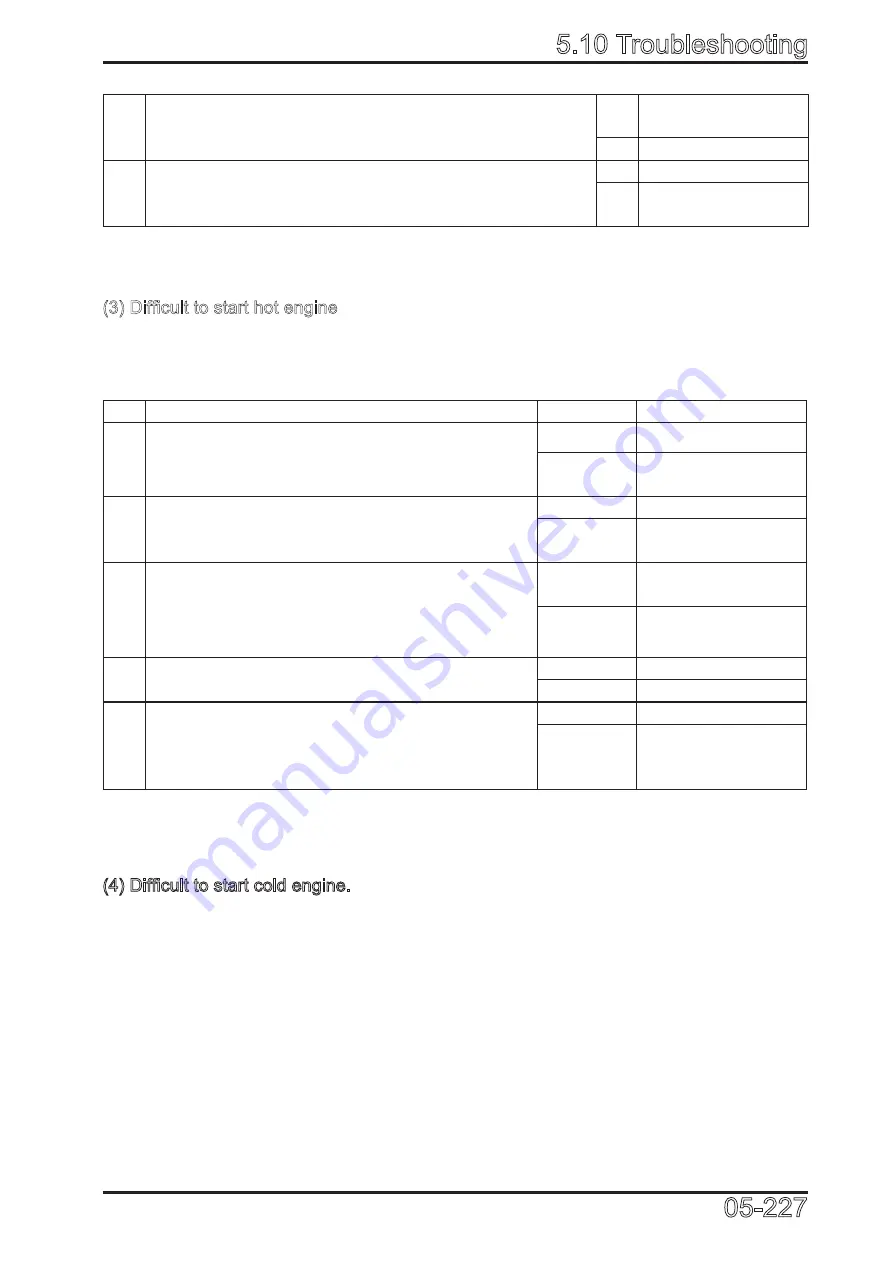
5.10 Troubleshooting
05-227
4
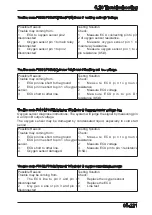
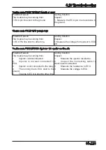
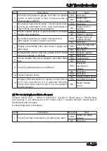
Check if cylinder pressure is sufficient
YES Eliminate engine
Mechanical failures
NO Next step
5
Use PDA to test, turn on ignition switch, check if power
supply of ECU pin 1 and pin 21 is normal; check if pin 2
and pin 17 works normally
YES Use PDA to check
NO Repair related
circuit
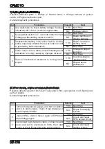
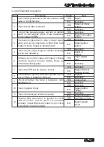
Item
Procedures
Results
Next
1
Connect fuel pump gauge, start engine, check
ifpressure is approximately 300kPa
YES
Next step
NO
Repair fuel supply
system
2
Disconnect high-tension cable, connect spark
tester and set its electrode to 5mm, then start
engine to check if blue and white spark appears
YES
Next step
NO
Repair ignition
system
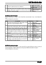
3
Disconnect water temp.sensor connector and
start engine to check if engine can start.(or use
one 300ohm resistance to replace water temp.
sensor)
YES
Repair wiring or
replace sensor
NO
Next step
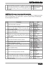
4 Check whether the failure happens right after
filling fuel
YES
Change fuel
NO
Next step
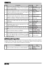
5
Connect PDA and switch on ignition to check
ECU-G1,F1,P4, and O4 pin if it is powered
normally; Check ECU-Q2,H3 and C3 pin if it is
connected to ground normally.
YES
Use PDA to check
NO
Repair related
circuit
(3) Difficult to start hot engine
General failure part (1)Water in fuel tank(2)fuel pump(3)water temp. sensor(4)Ignition
coil.
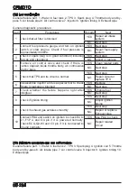
General diagnostic procedures:
(4) Difficult to start cold engine.
General failure part(1)water in fuel tank(2)Fuel pump(3)Engine temp. sensor(4)
Injector(5)Ignition coil(6)Throttlebody and by-pass(7)Mechanical parts of engine
General diagnostic procedures:
Summary of Contents for CF1000ATR 2018
Page 1: ...CFMOTO SERVICE MANUAL CF1000AU CF1000ATR CFORCE 1000 ...
Page 81: ...CFMOTO 05 6 5 1 4 EIN Location EIN Location Engine left side Engine right side 050601 050602 ...
Page 351: ...06 Vehicle chassis 06 41 6 7 3 Front and rear CV shaft disassemble view 064101 064102 ...
Page 363: ...Appendix A ...
Page 364: ...Appendix B ...
Page 365: ...Appendix C ...


