06 Vehicle chassis
06-5
060501
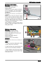
Foot brake master cylinder
Removal:
(See picture 060502)
Remove brake pedal
(See 2.6.6).
Remove the retainer pin and pin shaft 3.
Remove 2 bolts 4.
Remove the master cylinder 5.
Remove 2 bolts 6.
Remove oil cup 7
(See 060503).
Installation:
Reverse the removal procedure for
installation.
NOTE:
1. In order to avoid air entering the master
cylinder, keep it level at all times.
2. Keep the brake line routed properly and
ensure it is not, and cannot, be kinked.
3. After installation, bleed the brake system
anytime it has been repaired and check
brake performance.
6
7
Front brake master cylinder
Removal:
(See picture 060501)
Remove right hand guard.
Remove bolts 2.
Separate front brake master cylinder 1
from the handlebar. It's not necessary to
remove it if replacement is not required.
Installation:
Reverse the removal procedure for
installation.
NOTE:
Do not hang the master cylinder
by the brake line, keep the master cylinder
upright (not inclined) while installing it to
avoid air entering brake line. Keep the
brake line routed properly (refer to Chapter
1) and ensure it is not kinked.
After installation, bleed the brake system
anytime it has been repaired and check
brake performance.
060503
060502
5
4
3
4
1
2
2
Summary of Contents for CF1000ATR 2018
Page 1: ...CFMOTO SERVICE MANUAL CF1000AU CF1000ATR CFORCE 1000 ...
Page 81: ...CFMOTO 05 6 5 1 4 EIN Location EIN Location Engine left side Engine right side 050601 050602 ...
Page 351: ...06 Vehicle chassis 06 41 6 7 3 Front and rear CV shaft disassemble view 064101 064102 ...
Page 363: ...Appendix A ...
Page 364: ...Appendix B ...
Page 365: ...Appendix C ...

