06 Vehicle chassis
06-7
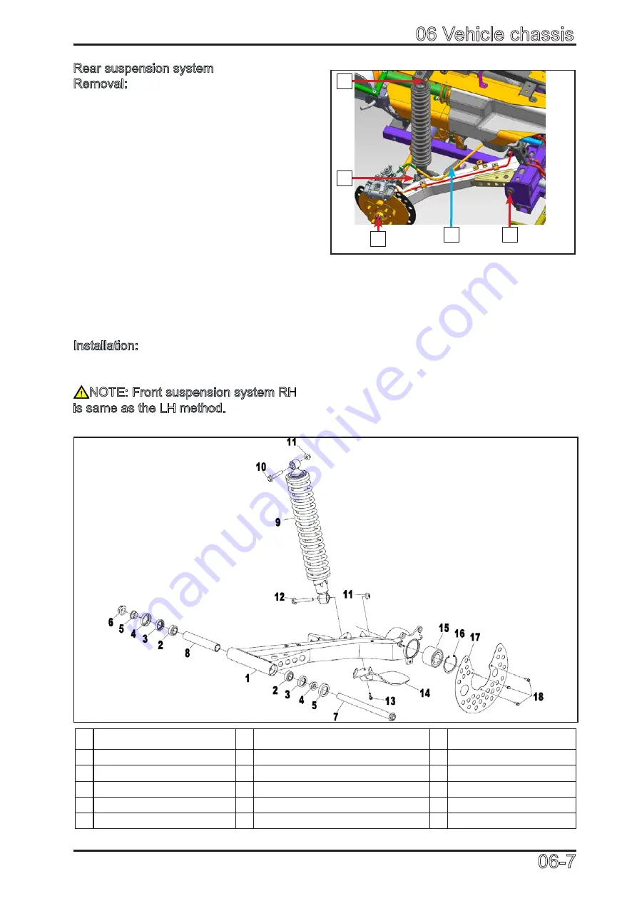
060701
Rear suspension system
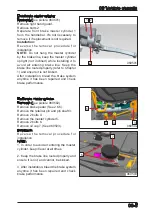
Removal: (See picture 060701, 060702)
Set the vehicle on flat ground. Use lifting
jack to lift up the vehicle and support on
the frame.
Remove the rear wheel.
Remove the rear brake caliper.
Remove the cotter pin and locking nut 3 on
CV shaft.
Remove rear wheel hub and brake disc
assembly.
Remove rear torsion bar ball pin nut 2.
Remove rear shock absorber mounting
bolt and nut 1. Remove shock.
Remove rear suspension arm bolt and nut
4.
Remove rear suspension arm from CV
shaft.
Installation:
Reverse the removal procedure for
installation.
NOTE: Front suspension system RH
is same as the LH method.
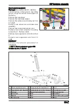
060702
1 Rear suspension arm
7 Suspension arm shaft bolt
13 Bolt
2 Suspension arm bearing 8 Suspension arm inner sleeve 14 Suspension guard
3 Oil seal
9 Rear shock absorber
15 Wheel bearing
4 Dust boot
10 Bolt
16 Retainer
5 Sleeve
11 Nut
17 Rear brake disc guard
6 Locking nut
12 Bolt
18 Bolt
1
4
3
2
1
Summary of Contents for CF1000ATR 2018
Page 1: ...CFMOTO SERVICE MANUAL CF1000AU CF1000ATR CFORCE 1000 ...
Page 81: ...CFMOTO 05 6 5 1 4 EIN Location EIN Location Engine left side Engine right side 050601 050602 ...
Page 351: ...06 Vehicle chassis 06 41 6 7 3 Front and rear CV shaft disassemble view 064101 064102 ...
Page 363: ...Appendix A ...
Page 364: ...Appendix B ...
Page 365: ...Appendix C ...

