06 Vehicle chassis
06-15
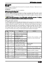
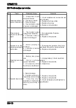
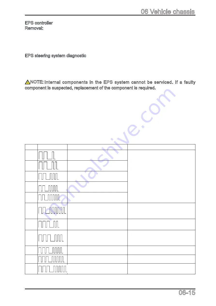
Code
Waveform
Diagnosis
Solution
21
Main sensor is disconnected
I n s p e c t w i r e h a r n e s s , w i r e
connectors, and connector pins
22
Main sensor output abnormal
(Voltage high or low)
23
Secondary sensor is
disconnected
24
Secondary sensor output
abnormal (Voltage high or low)
25
Discrepancy of the main and
secondary torque values
26
Main torque sensor phase
compensation is over limit
Replace EPS
controller
32
Motor running wrong
I n s p e c t w i r e h a r n e s s , w i r e
connectors, and connector pins
33
EPS controller current out of
service limit (Voltage high or
low)
Replace the EPS controller
34
Motor one side no power
Replace the EPS controller
35
Zero point run-out over limit
Replace the EPS controller
36
Motor open
I n s p e c t w i r e h a r n e s s , w i r e
connectors, and connector pins
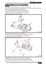
EPS controller
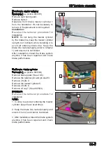
Removal:
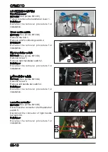
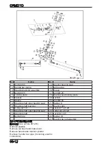
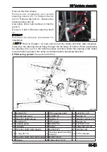
Remove body covering parts. Disconnect the connectors. Remove 3 M6 bolt 25, 26.
Remove EPS controller 27.
Installation
:
Reverse the removal procedure for installation.
EPS steering system diagnostic
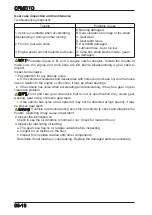
The EPS indicator light turns on when the vehicle is equipped with EPS. Under normal
conditions, EPS the indicator light remains on after turning the power switch on, but the
EPS will not work. The EPS indicator light turns off after the engine is started and the
EPS begins to work.
NOTE: Internal components in the EPS system cannot be serviced. If a faulty
component is suspected, replacement of the component is required.
EPS system fault code table
The EPS indicator light on the dashboard flashes when a fault occurs. At that time, do
not turn off the power, but instead observe the frequency of flashing and record the order
it displays. Refer to the table to find the code. Every fault code consists of two digits. A
long flash time that lasts two seconds indicates a multiple of ten digit (The first number)
and short flash time that lasts a second indicates a single digit (The second number).
The indicator light is off for three seconds between flash codes. Any time the power is
turned off, the fault code memory is erased and the fault condition must repeat.
Summary of Contents for CF1000ATR 2018
Page 1: ...CFMOTO SERVICE MANUAL CF1000AU CF1000ATR CFORCE 1000 ...
Page 81: ...CFMOTO 05 6 5 1 4 EIN Location EIN Location Engine left side Engine right side 050601 050602 ...
Page 351: ...06 Vehicle chassis 06 41 6 7 3 Front and rear CV shaft disassemble view 064101 064102 ...
Page 363: ...Appendix A ...
Page 364: ...Appendix B ...
Page 365: ...Appendix C ...

