3-36
CFMOTO
Intake temp and pressure sensor
Resistance inspection
●
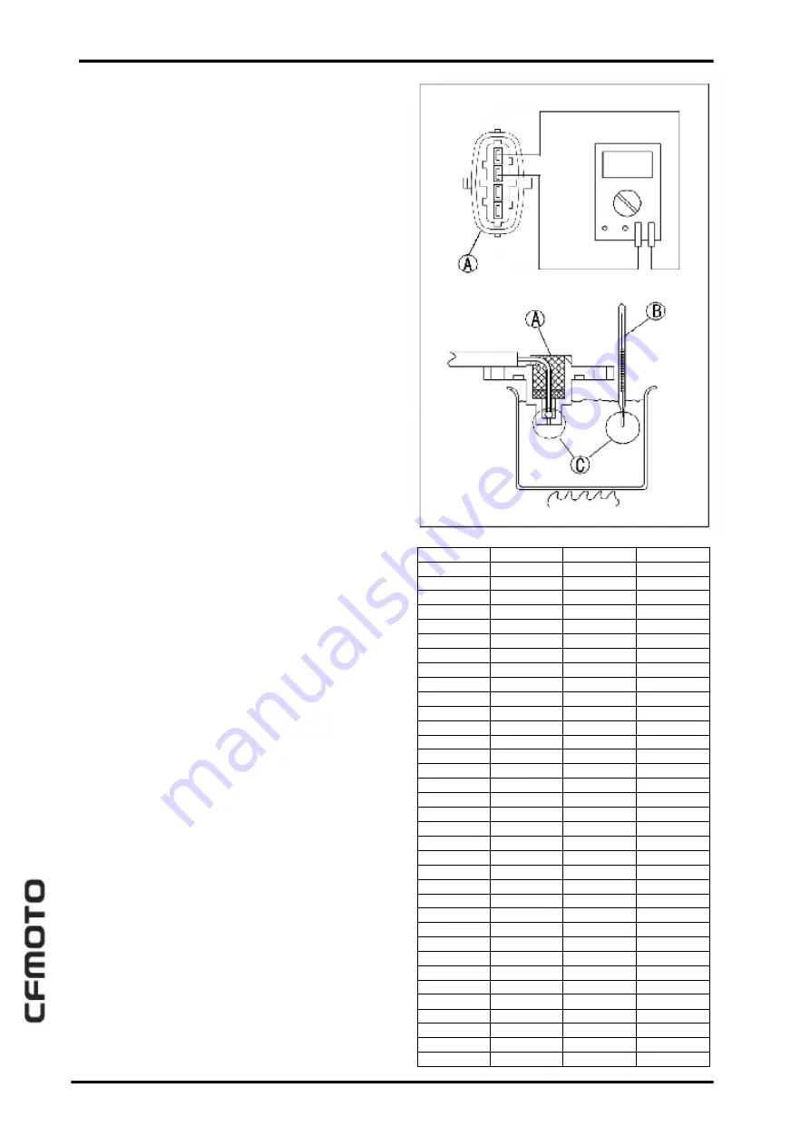
Remove the intake temp sensor.
●
Suspend the sensor [A] in a container of ma-
chine oil so that the heat-sensitiv e portion
issubmerged.
●
S us pend a t her m om et er [ B ] wi t h t he
heatsensitive portion [C] located in almost the same
depth with the sensor.
NOTE
●
The sensor and thermometer must not touch the
container side or bottom.
●
Place the container over a source of heat and
gradually raise the temperature of the oil while
stirring the oil gently for even temperature.
●
Using a hand tester, measure the internal resis-
tance of the sensor across the terminals at the tem-
peratures shown in the table.
Intake temp sensor resistance(See form on
the right)
Standard
:
24 16
~
2 58 3
Ω(
2 0
℃)
273.2
~
285.8
Ω
(
8 5
℃)
«
If the measurement is out of the range, replace the
sensor. If in the range but still trouble on. Replace
the ECU.
65±1
70±1
75±1
80±1
85±1
45±1
50±1
55±1
60± 1
10±1
15±1
20±1
25±1
30±1
35±1
40±1
-15± 1
-10± 1
- 5±1
0± 1
5±1
-35± 1
-30± 1
-25± 1
-20± 1
130 ±1
100 ±1
105 ±1
110 ±1
115 ±1
120 ±1
125 ±1
95±1
90±1
-40 ±1
Temp ( °C )
M i n R e s i s t a n
( O H M )
S ta nd ar d
R e s i s ta nd ( O H M )
4 266 1
3 181 0
23970
18258
140 39
10895
852 9.5
6 733 .5
535 8.1
429 5.9
48 153
35763
268 85
2 037 6
15 614
12078
9 428 .0
741 9.0
5886.7
4706.9
5 422 4
40118
3 001 5
22 695
1 733 3
13365
10399
8161 .4
6 457 .8
514 9.8
3 469 .2
282 0.9
2 308 .8
1904.0
158 6.1
1326.3
1113.0
9 37. 41
792 .27
671.90
5 71. 72
488.07
417 .98
3 59. 08
3 09.41
267.40
23 1.7 6
201.4 4
175 .52
153.18
1 34. 01
117.59
1 03. 12
9 1.80
3 0.5 8
379 1.1
30 74. 9
25 10. 6
2062 .9
1 715 .4
1431.8
1199.6
1008.6
851.10
720.65
6 12. 27
5 21.91
446.33
382 .89
329.48
284 .06
24 6.1 5
21 3.6 8
186.00
162.35
142.08
124.66
109.65
9 6.68
8 5.45
4137.3
3347.5
2726.8
22 35. 6
185 3.1
1 544 .1
129 1.5
1081.2
913 .15
772.28
655. 16
557.67
476.2 4
40 7.99
350.61
302.22
261.27
226.53
19 6.9 5
171 .88
1 50.4 3
13 2.0 0
1 16.12
1 02.3 9
90 .51
M a x R es is ta n
( O H M )
Summary of Contents for CF400-A 2017
Page 1: ...WWW CFMOTO COM Service manual CF400 A CF650 7B ...
Page 2: ...All right reserved ZHEJIANG CFMOTO POWER CO LTD Sep 2017 WWW CFMOTO COM ...
Page 31: ...2 13 2 Periodic maintenance 2 Special tool ...
Page 74: ...3 2 CFMOTO Exploded View ...
Page 148: ...4 2 Exploded view ...
Page 153: ...4 Cooling system 4 4 7 Special tool Bearing pressor Oil seal pressor ...
Page 168: ...5 3 5 Engine top 5 Exploded view ...
Page 170: ...5 5 5 Engine top 5 Exploded view ...
Page 174: ...5 9 5 Engine top 5 Special tool and sealant ...
Page 203: ...6 2 CFMOTO Exploded view ...
Page 206: ...6 Clutch 6 5 6 Clutch holder Sealant Special tool and sealant ...
Page 220: ...7 2 CFMOTO Exploded view ...
Page 222: ...7 4 CFMOTO Engine Oil Flow Chart ...
Page 223: ...7 Engine Lubrication system 7 5 7 Engine Oil Flow Chart ...
Page 237: ...8 2 CFMOTO Exploded view ...
Page 245: ...9 3 9 Crankshaft Transmission 9 Exploded view ...
Page 247: ...9 5 9 Crankshaft Transmission 9 Exploded view ...
Page 284: ...10 2 CFMOTO Exploded view ...
Page 300: ...11 2 CFMOTO Exploded view ...
Page 314: ...12 Breakingsystem 12 3 12 Exploded view Front break ...
Page 316: ...12 Breakingsystem 12 5 12 Exploded view Rear break ...
Page 319: ...12 8 CFMOTO Special tool Retainer plier Hand tester Jack Jack accessories ...
Page 335: ...13 2 CFMOTO Frontfork exploded view ...
Page 337: ...13 4 CFMOTO Rearswing armexplodedview ...
Page 350: ...14 2 CFMOTO Exploded view ...
Page 372: ...16 4 CFMOTO Parts location 1 2 3 4 5 6 7 8 9 10 11 12 13 14 15 16 17 18 19 20 22 21 ...
Page 402: ...Ignition System Ignition system wiring diagram 16 34 CFMOTO ...
Page 409: ...16 Electrical system 16 41 16 Starting system Starting system wiring ...


