8 Engine removal and installation
8
8-7
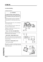
Engine Installation
Ÿ
Firstly, insert the rear engine mounting bolts [A] from
the left side of the engine.
Ÿ
Secondly, temporally tighten the right engine
mounting bracket bolts [B] and then the right front
engine mounting bolt [C].
○
Position the collar [D] as shown.
Ÿ
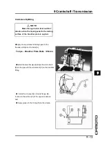
Thirdly, temporally tighten the left engine mounting
bracket bolts [E] and then the left front engine mount-
ing bolt [F].
Ÿ
Fourthly, temporally tighten the rear engine mount-
ing nuts [G]
Ÿ
Fifthly, tighten the rear engine mounting nuts.
Torque - Rear Engine Mounting Nuts
:44N
·
m(4.
5kgf
·
m,32ft
·
lb)
Ÿ
Sixthly, tighten the right engine mounting bracket
bolts.
Torque - Engine Mounting Bracket Bolts
:25N
·
m
(2.5kgf
·
m,18ft
·
lb)
Ÿ
Seventhly, tighten the right front engine mounting bolt.
Torque - Front Engine Mounting Bolt
44N
·
m(4.
5kgf
·
m,32ft
·
lb)
Ÿ
Eighthly, tighten the left engine mounting bracket
bolts.
Torque - Engine Mounting Bracket Bolts:
25N
·
m
(2.5kgf
·
m,18ft
·
lb)
Ÿ
Lastly, tighten the left front engine mounting bolt.
Torque - Front Engine Mounting Bolt
44N
·
m(4.
5kgf
·
m,32ft
·
lb)
Ÿ
Install the engine sprocket (see Engine Sprocket In-
stallation in the Final Drive chapter).
Ÿ
Run the leads, cables, and hoses correctly.(See the
leads,cables and hoses in appendix)
Ÿ
Install all removed parts(See related chapter)
Ÿ
Adjust:Throttle cable (See throttle controlling inspec-
tion in periodic maintenance chapter)
Clutch cable
(See clutch inspection in periodic main-
tenance chapter)
Drive chain (See drive chain tightness inspection in
periodic maintenance chapter)
Ÿ
Fill the engine oil (See engine oil replacement in pe-
riodic maintenance chapter)
Ÿ
Fill the coolant in the cooling system and drain out the
air from it.(See coolant replacement in periodic mainte-
nance chapter)
Ÿ
Adjust the idle speed(See idle speed adjustment in
periodic maintenance chapter)
Summary of Contents for CF400-A 2017
Page 1: ...WWW CFMOTO COM Service manual CF400 A CF650 7B ...
Page 2: ...All right reserved ZHEJIANG CFMOTO POWER CO LTD Sep 2017 WWW CFMOTO COM ...
Page 31: ...2 13 2 Periodic maintenance 2 Special tool ...
Page 74: ...3 2 CFMOTO Exploded View ...
Page 148: ...4 2 Exploded view ...
Page 153: ...4 Cooling system 4 4 7 Special tool Bearing pressor Oil seal pressor ...
Page 168: ...5 3 5 Engine top 5 Exploded view ...
Page 170: ...5 5 5 Engine top 5 Exploded view ...
Page 174: ...5 9 5 Engine top 5 Special tool and sealant ...
Page 203: ...6 2 CFMOTO Exploded view ...
Page 206: ...6 Clutch 6 5 6 Clutch holder Sealant Special tool and sealant ...
Page 220: ...7 2 CFMOTO Exploded view ...
Page 222: ...7 4 CFMOTO Engine Oil Flow Chart ...
Page 223: ...7 Engine Lubrication system 7 5 7 Engine Oil Flow Chart ...
Page 237: ...8 2 CFMOTO Exploded view ...
Page 245: ...9 3 9 Crankshaft Transmission 9 Exploded view ...
Page 247: ...9 5 9 Crankshaft Transmission 9 Exploded view ...
Page 284: ...10 2 CFMOTO Exploded view ...
Page 300: ...11 2 CFMOTO Exploded view ...
Page 314: ...12 Breakingsystem 12 3 12 Exploded view Front break ...
Page 316: ...12 Breakingsystem 12 5 12 Exploded view Rear break ...
Page 319: ...12 8 CFMOTO Special tool Retainer plier Hand tester Jack Jack accessories ...
Page 335: ...13 2 CFMOTO Frontfork exploded view ...
Page 337: ...13 4 CFMOTO Rearswing armexplodedview ...
Page 350: ...14 2 CFMOTO Exploded view ...
Page 372: ...16 4 CFMOTO Parts location 1 2 3 4 5 6 7 8 9 10 11 12 13 14 15 16 17 18 19 20 22 21 ...
Page 402: ...Ignition System Ignition system wiring diagram 16 34 CFMOTO ...
Page 409: ...16 Electrical system 16 41 16 Starting system Starting system wiring ...


