3
Palmgren Operating Manual & Parts List 9682090
SAFETY RULES (CONTINUED)
•
Adjust distance between wheel and tool rest to maintain 1/16”
or less gap.
•
Handle the workpiece correctly. Whenever possible, use tool
rest to support workpiece during grinding operation. Turn tool
off if it jams.
•
Always use guards and eyeshields.
•
Clean grinding dust from beneath tool frequently.
ASSEMBLY
Parts to be fastened to the unit should be located and accounted
for before assembly.
IMPORTANT:
Do not attempt assembly if parts are missing. Use this
manual to order replacement parts.
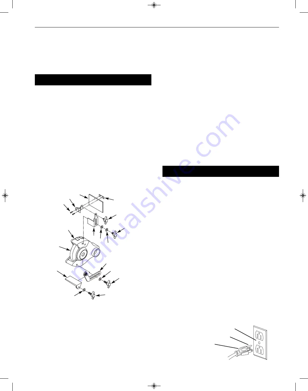
A Knob (2)
B Flat washer, M8 (6)
C Tool rest bracket (2)
D Tool rest (2)
E M10 Flat washer (2)
F Knob (2)
G Pan head screw, M5 x 10 (4)
H Upper eyeshield bracket (2)
I Eyeshield (2)
J Lower eyeshield bracket (2)
K Knob (2)
L Spark Deflector (2)
M Knob (2)
N Spring Washer, M10 (8)
TOOL REST ASSEMBLY
1) Place tool rest (D) over tool rest bracket (C) and secure in posi-
tion with knob (F) and flat washer (E).
2) Attach tool rest bracket (C) to the bottom of the wheel guard
(O) using knob (A) and flat washer (B). Make sure that the slot of
the bracket is located over the raised boss on the wheel guard.
Secure in position with knob.
3) Position tool rest (D) so that distance between tool rest (D) and
wheel (P) is less than 1/16”. Reposition angle of tool rest if nec-
essary. Secure all knobs.
•
Mount right tool rest in a similar manner.
EYESHIELD ASSEMBLY
•
Attach spark guard (L) to left wheel guard (O) using knob (M),
spring washer (N) and flat washer (B).
•
Mount left upper eyeshield bracket (H) to eyeshield (I) and
lower eyeshield bracket (J) using two pan head screws (G).
NOTE:
Left upper eyeshield bracket is stamped “L” for identification.
•
Slide knob (K) through hole at top of left spark deflector (L) into
upper eyeshield bracket (H) and secure in position.
•
Locate eyeshield in desired position for protecting operator and
secure all knobs and bolts.
•
Mount right eyeshield assembly in a similar manner.
DUST COLLECTION HOSE
•
A dust collector hose has been provided with grinder. Slide
hoses onto sides of T-connector and flanges. Mount the hose by
sliding the flanges at each end over the exhaust ports on the
left and right wheel guards. Attach 2½” shop vacuum hose to
collector hose. Be sure hose is mounted securely.
DANGER:
Be sure to empty shop vacuum of all flammable mate-
rial (flammable liquids and vapors, paper, wood, plastic, etc.) before
connecting vacuum to grinder. Hot sparks from grinder may ignite
flammable materials in shop vacuum.
INSTALLATION
MOUNT BUFFER (FASTENERS NOT INCLUDED)
•
Mount buffer to a solid horizontal surface.
•
To mount buffer to metal pedestal, align mounting holes with
corresponding holes in pedestal. Insert a 1/4-20 x 1¼” hex head
bolt with flat washer through base of buffer. From bottom of
pedestal, place a 1/4” flat washer and 1/4”-20 hex nut onto the
bolt. Tighten only until space between buffer base and pedestal
is 1/8”. Using second nut on each bolt, jam tighten against the
first to prevent loosening by vibration.
•
To mount buffer to wooden bench top, use 1/4 x 1¼” wood
screws with flat washers beneath heads. Tighten screws until
space between buffer base and bench top is 1/8”.
GROUNDING INSTRUCTIONS
WARNING:
Improper connection of equipment grounding con-
ductor can result in the risk of electrical shock. Equipment should
be grounded while in use to protect operator from electrical shock.
•
Check with a qualified electrician if grounding instructions are
not understood or if in doubt as to whether the tool is properly
grounded.
•
This grinder is equipped with an approved 3-conductor cord
rated at 300V and a 3-prong, grounding type plug (See Figure 2)
for your protection against shock hazards.
•
Grounding plug should be plugged directly into a properly in-
stalled and grounded 3- prong grounding-type receptacle (See
Figure 2).
J
G
O
P
C
B
N
B
D
E
F
A
K
L
M
I
H
Figure 1 – Left Tool Rest and Eyeshield Assembly
Figure 2 – 3-Prong Receptacle
Properly Grounded Outlet
Grounding Prong
3-Prong Plug
9682090_oipm_En013_9643557.01 __ 02-08-2019 . . . . 02/08/19 3:05 PM Page 3


