background image

User Notice

 When operating, the entire capacity of the cooperating indoor unit should be not larger 

than 150% of outdoor unit. Otherwise, it will cause the shortage of cooling (heating) capacity.

 A Breaker(or fuse) need to be installed in every indoor unit, and the capacity should 

in according with indoor unit’s electrical parameter; all the indoor units are required to be 
centralized controlled by a total Switch, this Switch can cut off the electric power supply in 
case of emergency. The Breaker(or fuse) on each indoor units have the function of short 
circuit prevention and abnormal overload avoiding, it should be connected in normal situation. 
The total switch controlling the  power supply of all the indoor units. Before clearing and 
maintenance job being carried out to the indoor units, it is very important to turn off the total 
power supply switch.

 In order to turn on the units successfully, the main power switch should be opened 8 

hours before the operation.

 After receiving the turn off signal, every indoor unit will continue to work for 20-70sec to 

make use of the rest cool air or the rest heat air in the heat exchanger, while preparing for the 
next operation. And this is normal.

 When the selected operating mode of the indoor unit are clash with the operating 

mode of the outdoor unit, the malfunction light will blink after 5s on the indoor unit or remote 
controller showing that the operation clash, then the indoor unit will stop. At this time, change 
the operation mode of the indoor unit to the one that would not clash with the outdoor operating 
mode to make the operation normal. The cooling mode is not clash with the dry mode, while 
the fan mode is not clash with any mode.

 The appliance shall not be installed in the laundry.

 An all-pole disconnection switch having a contact separation of at least 

1/8” (

3mm

in all 

poles 

should be connected in fixed wiring.

 Information regarding transport/storage temperature 

-13-131

°

F (

-25-55°C) is missing.

 Main switch provided by end user: main switch handle should be black or gray, it can be 

locked in “OFF” position with padlock.

 The main disconnection device should be explained in user manual and the height 

should be recommended at 

2-5.8ft (

0.6-1.7m

)

 over current protection is required(UL 1995,CSA

C22.2).

  The  cooling  range  of  the  unit  is  the  outdoor  environment  temp.

  23

~

11

F  (-5

~

48

°C

)

DB, the heating range of the unit( only for the heat pump type unit) is the outdoor environment 
temp. 

5

~

81

°

F (

-15~27°C

)

 WB.

Thank you for your selecting of 

Cooper&Hunter

 air conditioner, please read this 

usage and install instruction carefully and keep it well in order to use this unit 
correctly.

Summary of Contents for GKH(12)BA-D3DNA2A/I

Page 1: ...MULTI DUCTLESS INVERTER HEAT PUMP INSTALLATION MANUAL PANEL CASSETTE TYPE INDOOR UNIT Models GKH 12 BA D3DNA2A I GKH 18 BA D3DNA2A I...

Page 2: ...rating mode of the indoor unit are clash with the operating mode of the outdoor unit the malfunction light will blink after 5s on the indoor unit or remote controller showing that the operation clash...

Page 3: ...the refrigerant pipe 4 2 7 Drainage hose 5 2 8 Electrical wiring 7 2 9 Install the panel 8 3 Constitutes and Names of Parts of Compact Panel Cassette Type Indoor Unit 10 4 Working Temperature Range 1...

Page 4: ...ent Don t spray or smear any oil paint or insecticide on the surface of unit otherwise fire may be leaded 1 Do not refit the conditioner Please contact the agency or prefect ional personnel to repair...

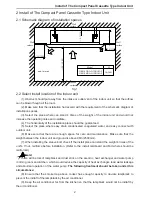
Page 5: ...Select the place where easy drain condensated coagulated water and easy connect with outdoor unit 6 Make sure that there are enough space for care and maintenance Make sure that the weight between the...

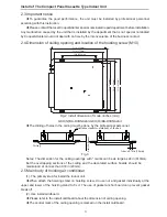
Page 6: ...3DNA2A I GKH 18 BA D3DNA2A I The drilling of holes in the ceiling must be done by the professional personnel Ceiling Installation stands for main body of the unit 6in 160 mm Above 0 78in 20mm Fig 3 No...

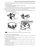
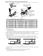
Page 7: ...break off and tighten the nut on it 6 Backout the install cardboard Fig 4 Note Please do tighten the nuts and bolts to prevent air conditioner break off 2 6 Connection of the refrigerant pipe When co...

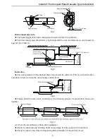
Page 8: ...iameter of the drain hose should be equal or bigger than the connection pipes The diameter of polythene pipe Outer diameter 1 25mm Surface thickness 1 16 1 5mm Drain hose should be short and drooping...

Page 9: ...tion The slant gradient of the attached drain hose should be within 3in 75mm so that the drain hole doesn t has to endure the unnecessary outside force Fig 9 Please install the drain hose according to...

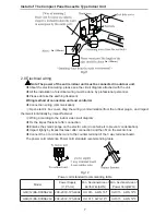
Page 10: ...ividually by impact fastener Wiring according to the indoor side circuit diagram Fix the impact fastener after connection Entwine the small sponge on the electric wire do entwine it to prevent condens...

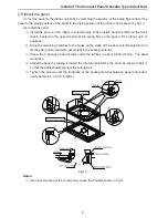
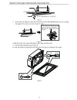
Page 11: ...p on the panel of the indoor unit 2 positions Hang the remaining 2 latches to the hooks on the sides of the indoor unit Be careful not to let the swing motor lead wire get caught in the sealing materi...

Page 12: ...height of the indoor unit As shown in fig 15 If the raising lever and drain hose are not affect can adjust the height of indoor unit by the hole on the corner of panel Gaps are not allowed Fig 15 Afte...

Page 13: ...Constitutes and Names of Parts of Compact Panel Cassette Type Indoor Unit 10 3 Constitutes and Names of Parts of Compact Panel Cassette Type Indoor Unit GKH 12 BA D3DNA2A I GKH 18 BA D3DNA2A I...

Page 14: ...e Outdoor side stae Dry bulb temp F C Wet bulb temp F C Dry bulb temp F C Wet bulb temp F C Rated Cooling 81 27 66 19 95 35 75 24 Max cooling 90 32 73 23 118 48 79 26 Min cooling 70 21 59 15 64 18 Rat...

Page 15: ...Add West Jinji Rd Qianshan Zhuhai Guangdong China 519070 MANUFACTURER GREE ELECTRIC APPLIANCES INC OF ZHUHAI www cooperandhunter us...

Reviews: