background image

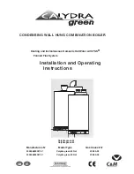
CONDENSING WALL HUNG COMBINATION BOILER

Heating and Instantaneous Domestic Hot Water with TSS®

Fanned Flue System

Installation and Operating

Instructions

Calydra green 24
Calydra green 30

c


Manufactures N°

Model Type

Gas Council N°

200906823037.31

Calydra green 24 Nat

47-980-25

200906826037.31

Calydra green 30 Nat

47-980-26

GB

IE


Summary of Contents for Calydra green 24

Page 1: ...us Domestic Hot Water with TSS Fanned Flue System Installation and Operating Instructions Calydra green 24 Calydra green 30 c Manufactures N Model Type Gas Council N 200906823037 31 Calydra green 24 Nat 47 980 25 200906826037 31 Calydra green 30 Nat 47 980 26 GB IE ...

Page 2: ... after sales service please return the guarantee registration card enclosed with the boiler without delay STATUTORY REQUIREMENTS The installation of this appliance must be carried out by a CORGI Registered person or other competent person and in accordance with the requirements of the Gas Safety Installation and Use Regulations In addition the installation must also comply with the current bylaws ...

Page 3: ...LLING THE BOILER 8 Method of positioning the boiler on th wall 8 Connecting the boiler to the system 8 Safety valve and condensats drains 8 Fitting the horizontal flue 8 6 ELECTRICAL CONNECTIONS 10 Making the Electrical Connections 10 7 COMMISSIONING AND TESTING 10 Pre commissioning 10 DHW 10 Central Heating 10 Lighting the boiler 10 By pass and pump 11 Post Commissioning 11 Handing over to the Ho...

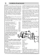
Page 4: ... fully automatic wall mounted low water content condensing combination boiler It is a room sealed fan assisted balanced flued appliance providing central heating and mains pressure domestic hot water on demand It has electronic ignition and is suitable for all modern electrical control systems The boiler is designed for sealed systems only and a circulating pump expansion vessel together with a pr...

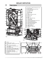
Page 5: ... thermistor 23 TSS Control thermistor 24 Overheat sensor 25 TSS mini cylinder 26 DHW pressure relief valve 49 Silencer 1 INSTALLER S INSTRUCTIONS 27 Display 28 Domestic Hot Water switch 29 Green indicator Domestic Hot Water mode ON 30 D H W temperature reducing key 31 D H W temperature increasing key DHW mode indicator 32 Central Heating switch 33 Green indicator Central Heating mode ON 34 Central...

Page 6: ...ly closed Maximum water capacity of Central Heating system The expansion vessel is pre charged to 0 7 bar 10 lb in2 The vessel is suitable for systems up to 145 litres capacity For systems of a greater capacity an additional expansion vessel will be required Refer to the chart Fig 6 and BS 7074 pt 1 or BS 5449 The minimum initial pressure of the system should be over 0 7 bar 1 to 1 5 bar is recomm...

Page 7: ... including other gas appliances on the same supply Combustion system protection The sulphur level contained in the gas should comply with the European Standards which are maximum 150 mg m3 for a short period in a year average level of 30 mg m3 during one year Electrical Supply The appliance requires an earthed 230V 50 Hz supply and must be in accordance with current I E E regulations It must also ...

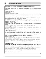
Page 8: ...elief valve tube is clear silicone It should terminate below the boiler over a tundish or 22 mm pipe see I Fig 4 which should in turn discharge safely outside the premises Care should be taken that it does not terminate over an entrance or window or where a discharge of heated water could endanger occupants or passers by External termination via condensate siphon The condensate drainage pipe shoul...

Page 9: ...9 5 A Fig 11 A A A Fig 9 Fig 10 L Fig 8 Fig 12 Installing the Boiler continued ...

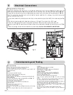
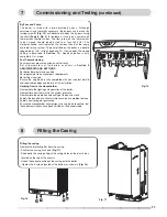
Page 10: ...1 C75 C74 C31 C38 C27 C26 C25 C1 J12 U12 5V J T S J 1 Fig 14 6 J T C S 7 Pre commissioning Ensure that the system has been adequately flushed Purge gas supply of air and test for soundness Carry out final electrical tests to ensure the correct polarity and earthing continuity DHW Open the main cold feed valve 43 Open all hot taps to purge the DHW system Check for water soundness Check flow rate at...

Page 11: ...t programmer to householder s requirements Set external controls Ensure the Log Book is fully completed with your contact details and required readings and details of the installation Handing Over to the Householder Demonstrate the lighting and operation of the boiler Demonstrate how to maintain the system pressure Demonstrate the operation and setting of the built in clock Explain the benefits of...

Page 12: ...u are at the first section pressing the key will change to the last section of the menu Setting a parameter in a section Press the setting key key of the C H side to enter the modification mode The 2nd and 3rd digits will flash Press the or keys on the DHW side to select the correct value then press the Setting key to accept this modification and to exit the setting mode The 2nd and 3rd digits wil...

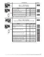
Page 13: ...layed if no default is recorded Menu 2 Boiler conditions Indicates the conditions or the configurations of the boiler Section Digit 1 Digits 2 and 3 Software version of display PCB 0 10 to 99 Flue type 2 1 FF variable speed Room thermostat is calling for heat 3 0 no 3 1 yes Theoretical position of the 3 way valve 4 0 DHW 4 1 CH DHW flow temperature in Celsius degrees 5 from 00 to 99 TSS temperatur...

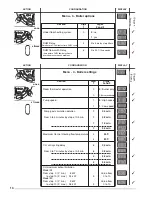
Page 14: ...eration 0 0 Burner only 0 1 Burner and pump Pump speed 1 0 High speed 1 1 Low speed Pump post circulation duration 2 0 0 min From 0 to 5 minutes by step of 0 5 min 2 0 5 min 2 1 0 min 2 5 0 min Maximum Central Heating flow temperature 4 50 C 4 80 C CH anti cycling delay 8 0 0 min From 0 to 7 minutes by step of 0 5 min 8 0 5 min 8 2 5 min 8 5 0 min CH maximum output limitation Model 24 From step 0 ...

Page 15: ...e to maximum output set in menu 4 section 9 Central heating temperature is displayed in celsius degrees The 3 dots indicate that the combustion rate control is ON at maximum output X X Switching off the combustion rate control mode press once press once press once press once Effect Display Locking conditions of the combustion rate control mode boiler in stand by mode D H W draw off room thermostat...

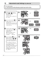
Page 16: ...r only or pump and burner change to Section 9 Adjustment of C H heat output Press the key on the DHW side times The display shows 906 which corresponds to 18 kW which is the factory setting 9 section 9 06 18 kW press the setting key on CH side once the 2nd and 3rd digits flash together Then press the or key on the DHW side to change the C H heat output step between 00 and 10 Press the setting key ...

Page 17: ...thermistor faulty open circuit 10 Domestic Hot Water thermistor faulty short circuit 11 Central Heating thermistor faulty open circuit 12 Central Heating thermistor faulty open circuit 18 Attempt to re ignite 20 Wiring problem 23 Fan speed too low 24 Fan control system defective 25 Thermistor cylinder open 26 Thermistor cylinder bypassed 29 Three way valve blocked in CH mode 31 Communication probl...

Page 18: ...Key to decrease the Central Heating temperature 35 Key to increase the Central Heating temperature 36 Green indicator Power ON 37 Orange indicator Burner ON 38 Red indicator Lock out flame failure 39 Reset button 12 Connecting bracket Taps shown in Open position Fig 21 40 Central Heating flow isolating valve 41 Domestic Hot Water outlet 42 Gas service tap 43 Water service tap 44 Central Heating re...

Page 19: ...ttom of the 3rd digit Switching on the Domestic Hot Water Press key 28 the green indicator 29 will light If there is no water demand the display will show the following graphic In case of draw off a square made of 4 digits will move clockwise on the display Keys 30 and 31 allow the adjustment of the temperature required for the Domestic Hot Water flow During the temperature setting operation the d...

Page 20: ... 4 C the pump and the burner will start 13 15 The manufacturer s guarantee is for 12 months from the date of purchase The guarantee is voidable if the appliance is not installed in accordance with the recommendations made herein or in a manner not approved by the manufacturer To assist us in providing you with an efficient after sales service please return the guarantee registration card enclosed ...

Page 21: ...ence in C H system or Insufficient pressure Gravity effect in the C H system Solution Control gas water and electrical supply fuses Follow the procedure in Section 8 Set up the room thermostat Wait for a few minutes Press the reset button 39 Fig 21 the red led will go out and the boiler will attempt to re light If red the indicator lights too frequently please call your local service centre Purge ...

Page 22: ...ter mains pressures Max operating 10 bar 145 Ib in2 10 bar 145 Ib in2 Flow limiter rate 8 l min 10 l min Compartment ventilation not required not required Natural gas G20 Gas rate C H max 2 64 m3 h 93 ft3 h 3 01 m3 h 106 ft3 h Gas rate DHW max 2 64 m3 h 93 ft3 h 3 01 m3 h 106 ft3 h Gas rate C H DHW mini 0 87 m3 h 31 ft3 h 1 m3 h 35 ft3 h Gas valve restrictor diameter without without Propane L P G ...

Page 23: ...23 ...

Page 24: ...d in this document Manufacturer Chaffoteaux Maury France Commercial subsidiary MTS GB Limited MTS Building Hughenden Avenue High Wycombe Bucks HP13 5FT Telephone 01494 755600 Fax 01494 459775 Internet www chaffoteaux co uk E mail info uk mtsgroup com Technical Support Help Line 0870 241 8180 Customer Service Help Desk 0870 600 9888 This appliance is suitable for Natural gas or LPG A gas conversion...

Page 25: ...as rate C H D H W min 0 64 kg h 0 73 kg h Gas valve restrictor diameter 4 40 mm 4 8 mm 24 kW 30 kW 24 kW 30 kW Heat gross input C H max 9 2 27 8 kW 10 4 31 6 kW Heat gross input D H W max 9 2 27 8 kW 10 4 31 6 kW Heat output C H 50 30 max 9 26 kW 10 30 kW Heat output C H 80 60 max 8 24 kW 9 28 kW Heat output DHW maxi 8 24 kW 9 30 kW C H operating temperature 80 C max 80 C max C H circuit pressures...

Page 26: ...tatic valves closed bar 0 1 3 4 42 43 44 41 40 45 46 47 1 2 3 4 5 6 8 11 12 13 14 7 15 10 9 16 1 Steel chassis complete with expansion vessel 2 Sealed chamber 3 Burner and heat exchanger assembly 4 Air gas connection 5 24 V modulating fan 6 Gas valve 7 Ignition electrode 8 Ionisation probe 9 Ignitor 10 Combustion products manifold 11 24 V transformer 12 Siphon 13 Electrical box 14 Pump 15 Secondar...

Page 27: ...e tap is opened at the gas meter and the main power is on Green indicator Power ON 36 3 Open the gas tap 42 The boiler is now ready to use Attention If the boiler remains off for a prolonged period of time air may collect in the gas pipes and can hinder the boilers initial attempts to light please refer to section 18 Incorrect Function Switching on the Central Heating Press key 29 the green indica...

Page 28: ...nti freeze function of the room thermostat if fitted To leave the room thermo stat anti freeze system operative please leave the Central Heating mode on The boiler is equipped with an automatic anti freeze system which is permanently on If the Central Heating temperature decreases below 7 C the pump will start If the Central Heating temperature decreases below 4 C the pump and the burner will star...

Page 29: ...nsures accurate temperature regulation When the tap is closed the burner may stay alight until the TSS cylinder is up to temperature Then the burner is extin guished and the pump stops The boiler will now stay in the hot water mode for 3 minutes to maintain temperature to ensure a fast response in the event of a subsequent hot water demand Priority will be given to a demand for hot water or re hea...

Page 30: ...oiler by pressing the reset key 39 Overheat detection If an overheat over 100 C is detected in the primary circuit by the sensor 23 the safety solenoids close and the fan stops The orange LED 37 extinguishes and the pump remains running for 3 minutes The reset will only be possible once the primary temperature has dropped below 76 C CALYDRA GREEN FUNCTIONAL DIAGRAM 17 18 19 20 21 23 24 26 27 28 29...

Page 31: ...urations of the boiler Section Digit 1 Digit 2 and 3 Software version of display PCB 0 10 to 99 Flue type 2 1 FF variable speed Room thermostat is calling for heat 3 0 no 3 1 yes Theoretical position of the 3 way valve 4 0 DHW 4 1 CH DHW flow temperature in Celsius degrees 5 from 00 to 99 TSS temperature in Celsius degrees 6 from 00 to 99 CH flow temperature in Celsius degrees 7 from 00 to 99 Soft...

Page 32: ...rmostat operation 0 0 Burner only 0 1 Burner and pump Pump speed 1 0 High speed 1 1 Low speed Pump post circulation duration 2 0 0 min From 0 to 5 minutes by step of 0 5 min 2 0 5 min 2 1 0 min 2 5 0 min Maximum Central Heating flow temperature 4 50 C 4 80 C C H anti cycling delay 8 0 0 min From 0 to 7 minutes by step of 0 5 min 8 0 5 min 8 2 5 min 8 5 0 min C H maximum output limitation Model 24 ...

Page 33: ...on rate to maximum output set in menu 4 sec tion 9 Central heating temperature is dis played in celsius degrees The 3 dots indicate that the combus tion rate control is ON at maximum output X X Switching off the combustion rate control mode press once press once press once press once press once Effect Display Locking conditions of the combustion rate control mode boiler in stand by mode D H W draw...

Page 34: ...vely Action on burner only or pump and burner change to section 9 Adjustment of C H heat output Press key on D H W side 9 times The display shows 906 which corresponds to the 18 kW which is the factory setting 9 section 9 06 18 kW press setting key on CH side once the 2nd and 3rd digits flash together Then press the or key on the D H W side to change the C H heat output step between 00 and 10 Pres...

Page 35: ...e gas valve assembly and the different transformers in the sealed chamber Check combustion chamber insulation panels for damage Check the lighting and ionisation electrodes condition Clean the burner Never use a metallic brush as this can damage the stainless steel Clean the heat exchanger Never use a metallic brush as this can damage the stainless steel Clean the siphon and pay attention to the a...

Page 36: ...mbly and the venturi from the fan assembly by loosening the two hexagonal head screws Reassemble in reverse order and replace all necessary gaskets 9 Gas section Carry out all operations mentioned in step 7 Unscrew the three screws secur ing the air gas connection pipe onto the gas valve assembly Separate the gas valve assembly and the venturi from the fan assembly by loosening the two hexagonal h...

Page 37: ...reverse order 22 Main control board Carry out step 1 as above and hinge down the electrical box by pressing the retaining tabs P on either side Remove wiring cover C Undo the 4 screws of the electrical rear panel and remove it Unplug all cables from the PCB remove the earth plug from the earth socket Hang out the main PCB Reassemble in reverse order 23 Display PCB Carry out step 1 and hinge down e...

Page 38: ... heating thermistor Check heating thermistor Ok No No No No Yes Yes Yes No No No Ok Ok Ok Ok means a test or a choice means an action means a group of actions error code displayed PLEASE CHECK THE FOLLOWING POINTS CAREFULLY BEFORE GOING THROUGH THE FAULT FINDING CHART Gas pressure Electric mains Minimum water pressure in the heating circuit over 0 8 bar All isolating valves have been opened Boiler...

Page 39: ...between the 2 PCBs Is the combution chamber full of conden sates Yes Check ionisation probe No Ok Drain and clean combustion cham ber siphon and drain pipes Yes Replace the ionisation probe No Stop water draw off Does DHW temper ature rise over 70 C Check DHW ther mistor No Ok Press on DHW key to switch off DHW mode Press on CH key to switch on CH mode and set CH tempera ture to maximum Press the ...

Page 40: ...90 R88 R66 R65 R64 R62 R7 R58 R59 R57 R24 R52 R53 R51 R6 R50 R49 R55 R5 R22 R79 R78 R77 R45 R43 R44 R42 R4 R39 R38 R35 R34 R3 R33 R32 R19 R18 R2 R16 R20 R21 R15 R14 R26 R25 R23 R13 R131 R130 C82 C81 T14 T13 D45 D44 RL12 R76 R12 R75 R74 R73 R72 R71 R70 R69 R68 R67 R129 R11 R128 R127 R116 R115 R122 R121 R120 R119 R117 R10 R1 Q1 P2 P1 MOV1 L1 J9 J10A J8 J6 J4 J3 J2 J1 FT1 F3A F3 F2A F2 F1A D9 D7 D6 D...

Page 41: ...CALYDRA GREEN DOMESTIC BOILERS CALYDRA GREEN 24 CALYDRA GREEN 30 B CALYDRA GREEN 1 Réf 82026 28c 07 03 GB ...

Page 42: ...EEN 82072 44 200 FAN 300 SEALED CASE 100 BURNER 213 117 112 114 116 314 311 305 228 304 313 212 222 109 115 108 102 110 104 227 107 231 315 229 118 121 123 116 122 119 119 205 303 101 304 309 639 308 202 313 230 203 ...

Page 43: ...306070 119 SCREW HX M 5 12 277797 1010131 121 O RING D 17 76 1 78 1308092 122 SCREW D 5 14 61308782 123 BARBED NIPLE 90 1309373 200 FAN ASSEMBLY 202 FLUE ADAPTOR 61309242 203 GASKET D 66 58 4 9 61310088 205 GASKET D 66 6 1306029 212 GASKET 1300262 213 PLUG KIT 1306698 222 OUTGOING FLUE BOX 1306028 227 TAPPING SCREW CBLSX D 4 2 12 5 1010847 228 TAPPING SCREW CBLSX D 6 3 13 277865 1010648 229 TAPPIN...

Page 44: ...4 B CALYDRA GREEN 82072 45 400 GAS SECTION 407 411 401 404 436 412 406 418 408 442 403 610 410 404 ...

Page 45: ...SECTION ASSY 61307584 GZ20 GAS SECTION ASSY 61310129 GZ20 403 SCREW CLXS M 4 30 61310333 404 SCREW HX M 5 12 277797 1010131 406 GASKET 1308335 407 FAN ASSY 1307585 408 SCREW CLSX M 5 12 1308327 410 GASKET 1306072 411 GASKET 1307587 412 SILENCER 61310121 418 CONNECTION 1012649 436 O RING D 22 2 6 E23502 21061 40 442 SCREW CBLSX M 4 12 1015222 24 30 ...

Page 46: ...86 591 537 585 510 504 502 561 504 531 502 595 592 593 543 516 518 404 582 521 526 586 507 511 569 584 506 504 502 590 520 597 596 553 552 589 583 587 542 594 522 540 564 504 404 504 500 HYDRAULIC BLOCK 572 574 588 567 805 571 573 550 558 6006 532 6007 6002 514 505 6003 510 570 548 551 548 418 535 101 ...

Page 47: ...T D 24 18 2 1 5 265091 22835 01 550 HEATING RETURN TUBE E23520 1014218 551 GAS TUBE 1307590 GAS TUBE 61309556 552 PLUG E23521 1015245 553 O RING D 8 9 1 9 264374 24164 13 558 PUMP LEAD 2 SPEEDS 1306995 561 BOTTOM INTERFACE SYSTEM E23522 1014172 564 O RING D 24 6 3 6 1009834 30 565 HEATING FILTER 1305560 567 CLIP 366887 30898 03 569 LIP SEAL 277860 1002249 570 HEATING RETURN TUBE 61310176 571 O RIN...

Page 48: ...70 R72 R30 R4 R27 R26 R24 R23 R22 R3 R21 R20 R140 R137 TH4 R2 R13 R12 R71 R1 1 R115 R127 C82 C81 T14 T13 R136 U11 R64 R10 R63 R61 R62 R60 R59 R126 R125 R120 R114 R110 R111 R109 R1 Q1 MOV1 L1 J9 J6 J4 J3 J2 FT1 F3 F2 F1 D9 D8 D7 D5 D34 D31 D30 D32 D4 D39 D38 D37 D36A D36 D33 D3 D29 D28 D27 D26 D23 D25 D24 D22 D21 D20 D2 D19 D18 D13 D12 D11 D10 D1 CTP1 C8 C49 R42 J11 C34 C7 J5 C53 C6 C52 C51 C76 C75...

Page 49: ...RIP 277877 1010152 613 TAPPING SCREW CBLSX L 10 1020509 614 ELECTRICAL BOX COVER 277879 1010007 615 PRINTED CIRCUIT BOARDS 1310357 617 ELECTRIC BOX PLATE 277882 1010006 618 PLUG E00269 1011316 621 TRANSMITTER OF LEDS 1306012 622 CONTROL PANEL 1306019 623 SIGHT GLASS 1303830 627 FUSE 250V 2A TEMPORIZED 277883 1003456 628 FUSE 250V 1A TEMPORIZED 1003634 629 FUSE 250V 1 25A TEMPORIZED 277884 1003635 ...

Page 50: ...10 B CALYDRA GREEN 82072 48 700 CHASSIS 800 FRONT CASE 714 713 712 709 706 703 704 706 701 705 801 711 805 710 806 813 802 815 807 ...

Page 51: ...67 1010170 706 TAPPING SCREW CBLSX D 6 3 19 1014516 709 FLEXIBLE PIPE KIT E23589 81824 710 CLIP 277848 1002406 711 O RING D 5 7 1 9 E00621 1009834 10 712 SHEET GASKET D 12 8 1 2 1308868 713 CLIP 277841 1010005 714 O RING D 8 9 2 7 E00605 1009834 14 800 FRONT CASE 801 TAPPING SCREW CBLSX D 4 2 9 5 277792 1010125 802 CASE E00622 1010016 CASE 61309874 805 PRESSURE GAUGE 1303158 806 DOOR 1306020 807 S...

Page 52: ...12 B CALYDRA GREEN 82072 49 900 JIG PLATE PIPE FITTING 907 908 909 901 902 904 906 903 905 927 931 939 940 941 937 910 943 939 921 922 925 919 918 917 920 918 939 920 917 918 936 923 947 938 ...

Page 53: ... DARK GREEN 277911 1002775 07 FLOW REGULATORE 8L MIN WHITE E23605 1002775 08 FLOW REGULATOR 10L MIN BLUE E00631 1002775 10 FLOW REGULATORE 12L MIN RED E23606 1002775 12 FLOW REGULATOR 14L MIN PINK 277911 1002775 14 FLOW REGUL 15L MIN PALE GREEN E23607 1002775 15 920 LOCK NUT H 1 2 277910 31139 921 SHEET GASKET D 24 18 2 1 5 265091 22835 01 922 HAND LEVER BLACK 1302611 923 HAND LEVER YELLOW 1302610...

Page 54: ...4 B CALYDRA GREEN 82072 50 1005 1000 FLUE CONNECTION 1001 1002 D80 80 V HORIZONTAL FLUE KIT DOUBLE FLOW FLUE KIT D60 100 D60 100 HORIZONTAL FLUE KIT 1003 1011 1018 1012 1014 1013 1017 1016 1015 1011 1011 1015 1020 1011 1022 1019 ...

Page 55: ... 1001 HORZ FLUE KIT D60 100 L 800 1309947 1002 V HORIZONTAL FLUE KIT D60 100 1309694 1003 VERTICAL FLUE KIT D80 125 1309693 1005 DOUBLE FLOW FLUE KIT D80 80 1309715 1011 GASKET Flue bend turret 1300258 1012 FLUE BEND 90 1309692 1016 SEALING RING TRIM 366995 62079 1017 HORZ TERMINAL D 60 100 L 800 61310156 1018 SCREW CBLXS D 5 16 61310811 24 30 ...

Page 56: ...A GREEN 5000 ACCESSORIES 5040 6000 MAINTENANCE 5020 5022 5021 5023 5030 5033 5035 ACOUSTIC KIT 5045 6002 6003 Simulating Descaling 6006 Spanner 6007 5002 GZ20 GZ31 5015 5014 Connection FIRST FITTING Connection REPLACEMENT ...

Page 57: ...ULNIER DUVAL FF 1303293 5020 SLEEVE 1018789 SLEEVE 61309802 5021 EXTREMITY CHOCK DRAUG DIV SIDE 1014400 EXTREMITY CHOCK DRAUG DIV SIDE 61311303 5022 CHOCK DRAUGHT DIVERTER SIDE E00655 1010080 CHOCK DRAUGHT DIVERTER SIDE 61309804 5023 SIDE CHOCK E00656 1010081 5030 JIG PLATE 1309325 5033 ROD PLATE E23679 1010932 5035 SOUNDPROOFING KIT 1305676 5040 USERS INSTRUCTIONS 1311238 5045 WALL SPACER KIT E23...

Page 58: ...18 ...

Reviews: