10
Making the Electrical Connections
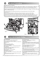
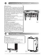
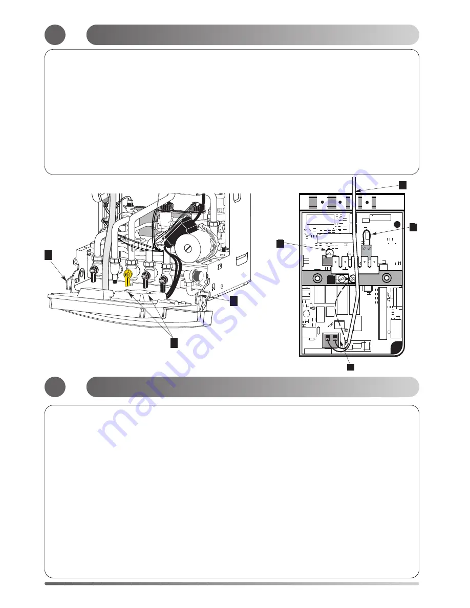
Hinge down the electrical box to gain access to the electrical connections. Push in the tabs P (fig 13) on either side of the
boiler and pivot the box forward. Undo the two retaining screws V , remove cover and remove cable clamp. C (fig 14)
Connect the live and neutral wires to the multipin plug leaving sufficient earth wire to connect to the earthing point
T fig 14 .
Note: The connections should be made so that should the lead be pulled from its anchorage, the current carrying wires
become taut before the earth wire.
If using a room thermostat or other external control, they can be connected in place of the link S on the multipin
Plug (see fig. 14).
Note: Use only controls designed for voltage free switching or 24V supply. Do not connect to a 230V supply.
Connect multipin plug into the socket on the printed circuit board. Secure the cable using the cable clamp and
replace the cover. NB The room thermostat options setting can be made before replacing the electrical box cover (1 fig.14).
All necessary settings for room thermostat operations are described in paragraph 9 ADJUSTEMENTS AND SETTINGS.
T
R
C
O
M
R
E
P
8
M
/A
VITESSE
1
1
1
1
1
1
BUS
1
CALYDRA
OFF ON
11
12
2
1.23
OFF ON
11
12
1
SW2
PROG
SW1
TA
1
T2A
1
MCD
1
230V
MOTEUR
RL6
R
13
3
C
28
T15
R
36
R
35
C
80
C79
T1
6
R
34
T12
T11
R107
R
33
R
13
0
R129
D43
U9
Z7A
R
13
2
R16
R15
R14
C84
C
83
R
6a
Z4A
C78
R
L1
3
C73
Z6
R7a
Z7
Z4
D46
T10
T9
RL8
R
L7
A
RL7
RL10
R
L2
A
R
L2
RL9
R
11
9
R
11
8
R113
R
9
R
8
R7
R
6
R
31
R
32
R
29
R27
R
25
R24
R23
R19
R
18
R
17
R
14
0
R137
TH
4
R13
R12
R1
1
R
11
5
C82
C
81
T14
T13
R136
TH3
U
11
R64
R10
R63
R59
R
12
8
R112
J9
J6
J7
J4
J3
J2
J1
F1
D
5
D31
D
30
D
32
D42
D41
D40
D35
D
36
A
D36
D
17
D16
D
15
D14
J1
1
C34
J5
C
52
C51
C75
C74
C
31
C
38
C27
C26
C25
C1
J12
U
12
+5
V
J
T
S
J 1
Fig. 14
6
J
T
C
S
7
Pre-commissioning
Ensure that the system has been adequately flushed.
Purge gas supply of air and test for soundness.
Carry out final electrical tests to ensure the correct polarity and
earthing continuity.
DHW
Open the main cold feed valve 40.
Open all hot taps to purge DHW system.
Check for water soundness.
Check flow rate at the bath tap is set correctly (see technical data).
Central Heating
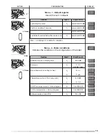
Open flow and return valves on the boiler 37 and 41 (Fig. 15)
Open the automatic air vent 18 (Fig. 2)
Fill system and vent radiators.
Set system pressure and remove filling loop.
Check for leaks.
Manually check pump is free to turn.
Switch on electrical supply.
Press the Central Heating switch 29 (Fig. 3) to switch on heating
mode.
Press the +
key
32 (Fig. 3) to set heating temperature to maximum.
Allow pump to run for several minutes.
Isolate the electrical supply.
Drain boiler and check water filter for installation debris.
Replace filter and recharge system.
Lighting the Boiler
Inspect the entire gas supply for soudness, including the gas meter,
the gas installation should be in accordance wiith the relevant
standards, in GB this is BS 6891 and in IE this is the current edition
of I.S.813.
Connect gas pressure gauge to test point 39 (Fig. 15).
Turn on the gas supply and boiler gas tap 39 (Fig. 15).
Ensure electrical supply is on.
Ensure all external controls are calling for heat.
Press on Central Heating switch 29 (Fig. 3) to switch on heating
mode.
Press the +
key
32 (Fig. 3) to set heating temperature to maximum.
The boiler will light. Allow the boiler to heat system.
Check the inlet gas pressure (working pressure) while boiler is
operating in hot water mode.(Refer to technicaldata).
Check the operation of the boiler controls and safety devices.(see
separate servicing leaflet for details).Set the by pass (refer to the
paragraph bellow).
Re-flush the system to remove any dissolved oils and fluxes.
Recharge system pressure and introduce any water treatment as
required.
P
V
P
Fig. 13
Electrical Connections
Commissioning and Testing
Summary of Contents for Centora green 24 Nat
Page 23: ...23 ...


