11
7
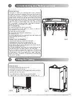
By pass and Pump
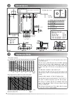
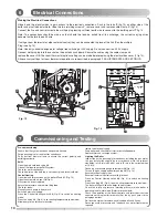
The boiler is fitted with a pre-adjusted by pass. Although
adjustment is not normally necessary, the by pass can be reset by
turning screw D (fig. 15 ) anticlockwise to open the by-pass using
the chart below for guidance. If used on a system with thermostatic
radiator valves, the flow rate with the thermostatic valves closed
should be adjusted to at least 300 l/hr. The enclosed charts indicate
the residual head of the pump available for the system. The pump
fitted on the boiler is a double speed model. (GV = High speed and
PV = low speed). The speed setting is described in chapter 9.
Speed selection is only available in C.H. mode.
Post Commissioning
Ensure system pressure has been set correctly.
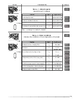
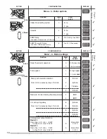
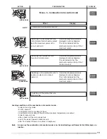
Set all parameters of the boilers as shown in chapter 9
ADJUSTMENTS AND SETTINGS.
Set boiler thermostat and controls.
Set programmer to householder’s requirements.
Set external controls.
Ensure the Logbook is fully completed with your contact details and
required readings and details of the
installation.
Handing Over to the Householder
Demonstrate the lighting and operation of the boiler.
Demonstrate how to maintain the system pressure.
Demonstrate the operation and setting of the built-in clock.
Explain the benefits of annual maintenance by a competent person.
Explain how to register guarantee.
Ensure the Householder countersigns the Log Book to confirm that
these demonstrations have been carried out and understood.
For IE, it is necessary to complete a “Declaration of Conformity” to
indicate compliance to I.S.813. An example of this is given in the
current edition of I.S.813. An example of this is given in the curent
edition of I.S.813. in addition it is necessary to complete the
“Benchmark” Log Book.
T
T
1
2
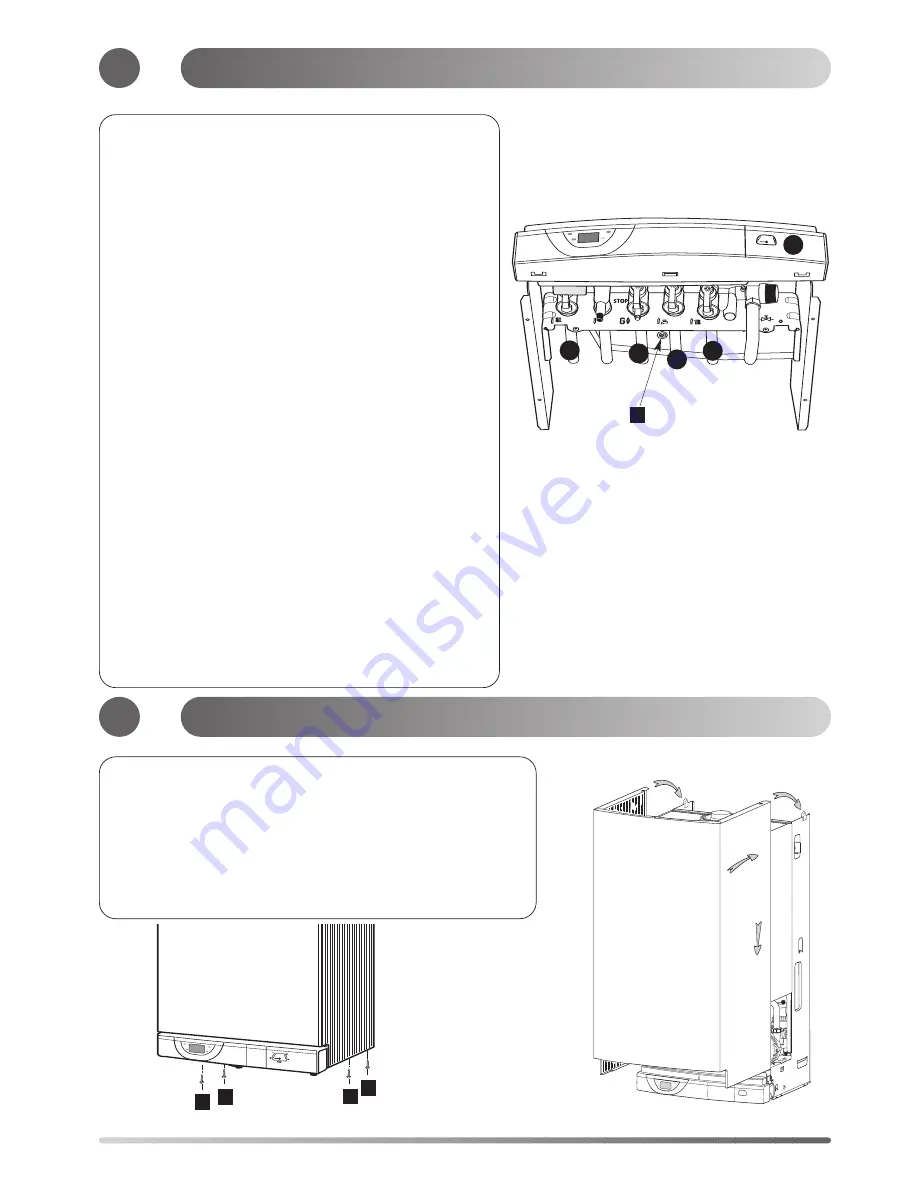
Fig. 17
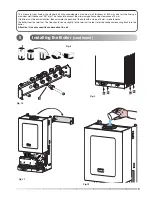
Fitting the casing
Remove the protecting film from the casing :
- Position the casing as shown fig. 17
- Slide down the casing and put the casing holes on the plastic pins
located on the top of the chassis
- Control the correct position of the casing onto the boiler
- Tighten the 4 screws located at the bottom as shown in fig. 16.
8
A A
A
A
Fig.16
bar
0
1
3
4
Fig. 15
D
16
37
39
40
41
Commissioning and Testing
(continued)
Fitting the Casing
Summary of Contents for Centora green 24 Nat
Page 23: ...23 ...


