background image

7.0  Appendix A - Maintenance Guide

13

7.1 Mechanical System

The machine should be lubricated every 6 months, and the knife should be changed when cut quality
becomes unacceptable.

7.1.1 Lubrication

Grease

Disconnect main power.
See Section 2.2 Power Lockout Procedure.

1.  Remove the top cover by removing the four screws that mount it to the machine base.

Two are located in the rear, and two are located in the front.  The hood must be in the up
position in order to remove the two front screws.

2.  After removing the mounting screws, lift the top cover straight up until it clears the frame

plate inside.  Set aside the top cover and mounting screws.

3.  Brush high-pressure grease onto the exposed knife bar and knife bar bearing surfaces.
4.  Brush high-pressure grease onto the exposed surfaces of the guide blocks on each end

of the clamp as shown in Figure 3.

5.  Apply light machine oil to the clamp cylinder mounting pin and pull down bar mounting

screws on the clamp as shown in Figure 3.

Figure 3- Rear Gib Lubrication

6.  Apply light machine oil to all four knife link pins as shown in Figure 4- Front Gib

Lubrication on page 14.

7.  Remove left rear panel.

Oil


NOTICE: UNSUPPORTED PRODUCT! 

NO TECHNICAL SUPPORT AVAILABLE!


NO REPAIR PARTS AVAILABLE! 


Summary of Contents for 99100

Page 1: ...ation to any Challenge product is not authorized by The Challenge Machinery Company The availability of these manuals is solely for the purpose of providing reference information for the products This...

Page 2: ...ld and Serviced by The Challenge Machinery Company 6125 Norton Center Drive Norton Shores MI 49441 6081 USA ChallengeMachinery com Serial Numbers 99100 Up INSTRUCTION AND PARTS MANUAL NOTICE UNSUPPORT...

Page 3: ...is manual Also be sure to fill out the warranty card accompanying this manual and return it DIRECTLY TO CHALLENGE If you bought a used machine it is important to have the following information on reco...

Page 4: ...ustment 16 7 1 6 Backgauge Preset Position Adjustment 16 7 2 Hydraulic System 16 7 2 1 Hydraulic Fluid Check 16 7 2 2 Replacing Hydraulic Fluid 17 7 2 3 Hydraulic Fluid Compatibility List 18 7 2 4 Oil...

Page 5: ...ematic 35 8 2 2 EE 2895 Rev B Panel Assembly Electrical Controls 36 8 2 3 EE 2895 Panel Assembly Electrical Controls Parts List 37 8 2 4 S 1781 85 Fuse Replacement Label 38 8 3 Hydraulic 39 8 3 1 H 54...

Page 6: ...orming maintenance See Section 2 2 Power Lockout Procedure Observe all caution labels on this machine Be extremely careful when handling knives Always use the guarded knife lifter provided in the tool...

Page 7: ...is symbol If this label is lost from the machine it should be replaced The item number and location of this label can be found in section 8 1 11 Main Assembly Finish and Parts List SHOCK HAZARD Discon...

Page 8: ...des 41121 Felt Washer 4 5064 Cut Stick Hook 1 W 107 7 32 Hex T Wrench 1 W 137 5 32 Hex Wrench 1 W 141 1 8 Hex Wrench 1 36134 Pocket Pull Handle 4 E 889 35 1 Amp Slo Blo Fuse 1 E 889 32 10 Amp Slo Blo...

Page 9: ...kN Clamping Force 785 lbs 3 5 kN Overall Height 22 4 in 56 8 cm Overall Width 23 5 in 59 7 cm Overall Length 34 4 in 87 4 cm Net Weight 230 lbs 104 kg Shipping Weight 250 lbs 113 kg Miscellaneous Spe...

Page 10: ...create a tipping hazard If a stand is required purchase a Challenge stand P N 35470 Make sure to install the 4 screws from the tool kit into the top of the stand to prevent the machine from being pus...

Page 11: ...lock the backgauge in position 6 3 Load Paper Lift the front hood and jog the stock against the backgauge Challenge recommends centering the stock on the backgauge to ensure square cutting The side g...

Page 12: ...lot pull the remaining portion out of the slot by hand 3 Rotate or flip the stick until a new surface is oriented such that it would lie under the knife when reinserted into the slot 4 If all surfaces...

Page 13: ...the express understanding that they are to replace parts found missing or no longer serviceable on equipment designed and or manufactured at Challenge The Challenge Machinery Company assumes no liabi...

Page 14: ...ng screws lift the top cover straight up until it clears the frame plate inside Set aside the top cover and mounting screws 3 Brush high pressure grease onto the exposed knife bar and knife bar bearin...

Page 15: ...nging the Knife As the knife wears the quality of cut decreases The knife cannot be reground It must be replaced with a new one Disconnect main power See Section 2 2 Power Lockout Procedure Even worn...

Page 16: ...nd place the new knife and scabbard on the tabletop The top of the knife should face the knife bar 3 Remove the scabbard screws 4 Place all fingers on the top edge of the scabbard and thumbs in the ta...

Page 17: ...up position Do not over tighten the plunger Over tightening the plunger will cause undue wear 7 1 6 Backgauge Preset Position Adjustment Use the following instructions to set the forward backgauge li...

Page 18: ...S 1991 3 See Section 7 2 3 for a compatibility list DO NOT OVERFILL 6 Screw the filler cap back into the reservoir and replace all covers 7 2 2 Replacing Hydraulic Fluid The hydraulic fluid should be...

Page 19: ...s 4 If the replacement washers do not have a cut in them then cut through one side of each allowing them to be opened and fit onto the cylinder rod 5 Wipe any obvious leakage from the cylinder and kni...

Page 20: ...7 0 Appendix A Maintenance Guide 19 NOTICE UNSUPPORTED PRODUCT NO TECHNICAL SUPPORT AVAILABLE NO REPAIR PARTS AVAILABLE...

Page 21: ...8 0 Appendix B Parts List 20 8 0 Appendix B Parts List 8 1 Mechanical 8 1 1 Main Assembly Arch Cover Hood NOTICE UNSUPPORTED PRODUCT NO TECHNICAL SUPPORT AVAILABLE NO REPAIR PARTS AVAILABLE...

Page 22: ...8 0 Appendix B Parts List 21 8 1 2 Main Assembly Arch Cover Hood Parts List NOTICE UNSUPPORTED PRODUCT NO TECHNICAL SUPPORT AVAILABLE NO REPAIR PARTS AVAILABLE...

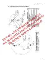
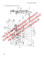
Page 23: ...8 0 Appendix B Parts List 22 8 1 3 Main Assembly Frame Front View NOTICE UNSUPPORTED PRODUCT NO TECHNICAL SUPPORT AVAILABLE NO REPAIR PARTS AVAILABLE...

Page 24: ...8 0 Appendix B Parts List 23 8 1 4 Main Assembly Frame Front View Parts List NOTICE UNSUPPORTED PRODUCT NO TECHNICAL SUPPORT AVAILABLE NO REPAIR PARTS AVAILABLE...

Page 25: ...8 0 Appendix B Parts List 24 8 1 5 Main Assembly Frame Rear View NOTICE UNSUPPORTED PRODUCT NO TECHNICAL SUPPORT AVAILABLE NO REPAIR PARTS AVAILABLE...

Page 26: ...8 0 Appendix B Parts List 25 8 1 6 Main Assembly Frame Rear View Parts List NOTICE UNSUPPORTED PRODUCT NO TECHNICAL SUPPORT AVAILABLE NO REPAIR PARTS AVAILABLE...

Page 27: ...8 0 Appendix B Parts List 26 8 1 7 Main Assembly Base NOTICE UNSUPPORTED PRODUCT NO TECHNICAL SUPPORT AVAILABLE NO REPAIR PARTS AVAILABLE...

Page 28: ...8 0 Appendix B Parts List 27 8 1 8 Main Assembly Base Parts List NOTICE UNSUPPORTED PRODUCT NO TECHNICAL SUPPORT AVAILABLE NO REPAIR PARTS AVAILABLE...

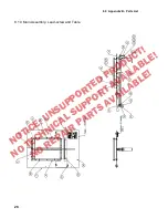
Page 29: ...8 0 Appendix B Parts List 28 8 1 9 Main Assembly Lead screw and Table NOTICE UNSUPPORTED PRODUCT NO TECHNICAL SUPPORT AVAILABLE NO REPAIR PARTS AVAILABLE...

Page 30: ...8 0 Appendix B Parts List 29 8 1 10 Main Assembly Lead screw and Table Parts List NOTICE UNSUPPORTED PRODUCT NO TECHNICAL SUPPORT AVAILABLE NO REPAIR PARTS AVAILABLE...

Page 31: ...8 0 Appendix B Parts List 30 8 1 11 Main Assembly Finish and Parts List NOTICE UNSUPPORTED PRODUCT NO TECHNICAL SUPPORT AVAILABLE NO REPAIR PARTS AVAILABLE...

Page 32: ...8 0 Appendix B Parts List 31 8 1 12 Main Assembly Controls NOTICE UNSUPPORTED PRODUCT NO TECHNICAL SUPPORT AVAILABLE NO REPAIR PARTS AVAILABLE...

Page 33: ...8 0 Appendix B Parts List 32 8 1 13 50025 Bell Crank Assembly NOTICE UNSUPPORTED PRODUCT NO TECHNICAL SUPPORT AVAILABLE NO REPAIR PARTS AVAILABLE...

Page 34: ...8 0 Appendix B Parts List 33 8 1 14 50025 Bell Crank Assembly Parts List NOTICE UNSUPPORTED PRODUCT NO TECHNICAL SUPPORT AVAILABLE NO REPAIR PARTS AVAILABLE...

Page 35: ...8 0 Appendix B Parts List 34 NOTICE UNSUPPORTED PRODUCT NO TECHNICAL SUPPORT AVAILABLE NO REPAIR PARTS AVAILABLE...

Page 36: ...8 0 Appendix B Parts List 35 8 2 Electrical 8 2 1 E 2896 Basic Machine Schematic NOTICE UNSUPPORTED PRODUCT NO TECHNICAL SUPPORT AVAILABLE NO REPAIR PARTS AVAILABLE...

Page 37: ...8 0 Appendix B Parts List 36 8 2 2 EE 2895 Rev B Panel Assembly Electrical Controls NOTICE UNSUPPORTED PRODUCT NO TECHNICAL SUPPORT AVAILABLE NO REPAIR PARTS AVAILABLE...

Page 38: ...8 0 Appendix B Parts List 37 8 2 3 EE 2895 Panel Assembly Electrical Controls Parts List NOTICE UNSUPPORTED PRODUCT NO TECHNICAL SUPPORT AVAILABLE NO REPAIR PARTS AVAILABLE...

Page 39: ...8 0 Appendix B Parts List 38 8 2 4 S 1781 85 Fuse Replacement Label NOTICE UNSUPPORTED PRODUCT NO TECHNICAL SUPPORT AVAILABLE NO REPAIR PARTS AVAILABLE...

Page 40: ...8 0 Appendix B Parts List 39 8 3 Hydraulic 8 3 1 H 549 Hydraulic Schematic NOTICE UNSUPPORTED PRODUCT NO TECHNICAL SUPPORT AVAILABLE NO REPAIR PARTS AVAILABLE...

Page 41: ...List 40 8 3 2 H 549 and H 549 1 Hydraulic Power Unit The parts listed on this drawing replace parts for both the 60 Hz and 50 Hz models NOTICE UNSUPPORTED PRODUCT NO TECHNICAL SUPPORT AVAILABLE NO RE...

Page 42: ...d Check b The wall outlet may not have sufficient power if other equipment is operating on the same line Try another outlet on a different line c The knife may be dull Change the knife See Section 8 1...

Page 43: ...11 16 17 5 mm thick piece of material underneath the center of the clear cover at the front edge of the front table 7 Lift the hood all the way up then bring it down to rest on the 11 16 thick materia...

Page 44: ...NOTES NOTICE UNSUPPORTED PRODUCT NO TECHNICAL SUPPORT AVAILABLE NO REPAIR PARTS AVAILABLE...

Page 45: ...Copyright 2000 2006 by The Challenge Machinery Company F 120 NOTICE UNSUPPORTED PRODUCT NO TECHNICAL SUPPORT AVAILABLE NO REPAIR PARTS AVAILABLE...

Reviews: