background image

9.0  Parts List & Sequence of Operations

70

9.10 Hydraulic Power Unit Assembly

H-507-( ) Rev. E

Summary of Contents for Titan 265

Page 1: ...Provided By http www MyBinding com http www MyBindingBlog com CHALLENGE TITAN 265 PAPER CUTTER Instruction Manual Serial Numbers 001314 Up...

Page 2: ...000 TITAN 265 PAPER CUTTING MACHINE Sold and Serviced by The Challenge Machinery Company 1433 Fulton Avenue Grand Haven MI 49417 1594 USA ChallengeMachinery com Serial Numbers 001314 Up INSTRUCTION AN...

Page 3: ...le Take a few minutes right now to RECORD YOUR MACHINE SERIAL NUMBER in the space provided on the front cover of this manual Also be sure to fill out the warranty card accompanying your machine and re...

Page 4: ...20 6 1 Power Main Switch 20 6 2 Start Up 20 6 3 Making a Cut Using Two hand cut buttons 21 6 4 Making a Cut Using Front guard 21 6 5 Jogging Aid 21 6 6 Knife Change Alarm and Lubrication Alarm 22 6 7...

Page 5: ...ne Maintenance 45 8 4 1 Weekly 45 8 4 2 Monthly 45 8 4 3 Yearly 45 8 5 Checking Changing the Hydraulic Fluid 45 8 5 1 Recommended Hydraulic Oils 46 8 6 Oil and Grease 48 8 7 Adjustments 48 8 7 1 Backg...

Page 6: ...Operation 78 9 17 Cut Button Assembly 79 9 18 Control Console Assembly 80 9 19 Control P C Assembly 81 9 20 Power Panel Label 82 9 21 Fuse Value and Function 83 9 22 Knife Latch Assembly 84 9 23 Line...

Page 7: ...nted on this cutter Keep foreign objects off table and away from cutter blade BE EXTREMELY CAREFUL when handling and changing the cutter knife Severe lacerations or dismemberment could result from car...

Page 8: ...EA Disconnect power before cleaning servicing or making adjustments not requiring power Do not alter safety guards or devices they are for your protection Replace all guards Do not operate with any gu...

Page 9: ...das en esta guillotina No permita que objetos estranos esten en la mesa o cerca de la cuchilla cortadora TENGA SUMO CUIDADO al tocar y cambiar la cuchilla Heridas severas y hasta desmembramiento puede...

Page 10: ...321 6 Washer 3 8 Plain 8 S 1859 1 Shim 005 12 S 1088 5 Wood Screw 10 x 5 8 8 20 2150 4 Tool Kit 1 H 6918 608 Knife Bolts 3 8 16 x 1 6 8815 Knife Washers Special 6 5064 Cutting Stick Puller 1 S 1245 5...

Page 11: ...lbs 861 kg Electrical 208 230 Volts 10 30 Amps 1 Phase 60 Hz AC Service size 40 Amps Sound Emission A weighted sound pressure level measured in an enclosed room at operator level 6 feet 183 cm Machine...

Page 12: ...earance to do this carefully slit the carton down the side and then unwrap it from around the cutter Remove the accessory box Remove the lag screws that secure the machine to the skid Cut shipping str...

Page 13: ...nt guard and foot treadle removed it will fit through a 32 81 3 cm opening 5 5 Removing the table Make sure the knife has been removed from the machine and that the knife and clamp are in the up posit...

Page 14: ...tor junction box cover and disconnect the wires to the motor Figure 4 Remove the leadscrew cover and the nylon tyraps that are attached to the bottom of the table The motor wires and encoder wires sho...

Page 15: ...disconnected With the lower front cover removed use an open end wrench to remove the two cables attached to the base at the foot treadle These cables hold the foot treadle up Remove the long bracket...

Page 16: ...st be readjusted see the Accuracy Adjust section on page 27 and the Squaring the Backguage section on page 49 5 9 Installing Extension Tables NOTE The power should be connected to the machine before i...

Page 17: ...e 11 Add fluid if necessary but avoid overfilling For more information about checking and changing the hydraulic fluid including a cross reference chart of approved fluids see the Recommended Oils sec...

Page 18: ...Up For satisfactory operation be sure that your cutter is wired for the correct phase and voltage and has adequate power The correct electrical specifications are shown on the machine s serial number...

Page 19: ...t hand corner of the machine rear Secure it with a conduit connector 4 Use a wire nut to join the incoming ground wire with the green yellow or green wire found in the junction box 5 Use wire nuts to...

Page 20: ...AZARD Always disconnect power at main power panel before working on the cutter Lock it out to prevent accidental power up See Power Lockout Procedure page 6 Bulb replacement 1 Make sure power is off a...

Page 21: ...de section on page 26 To restore power to the display and line lights press any button on the keyboard or press any cut button or lift up the front guard if equipped 6 2 Start Up Once power has been t...

Page 22: ...place the paper against the backgauge and left side guide If the cut will leave strips of paper less than 2 1 8 wide place the paper against the right side guide This will prevent the strips from get...

Page 23: ...To reset either alarm or to change the knife alarm value see the Knife Count section on page 27 The lube alarm value is factory set at 2 500 cuts and cannot be changed NOTE The alarms do not prevent n...

Page 24: ...position and programmed send values in inches e g 5 250 inch fractions to the nearest 1 64 e g 5_1 4 or millimeters e g 133 3 6 9 3 Send Key The SEND key is used to send the backgauge to any valid po...

Page 25: ...led as A B C and D The definition for these keys change depending on the operating mode The function of the key can be found on the bottom of the display screen 6 9 9 Arrow Keys The four arrow keys ca...

Page 26: ...nd the backgauge 2 forward from its current position just press 2 and SEND The send mode screen can also be used for doing math calculations that are larger than the backgauge s reverse limit In this...

Page 27: ...ameter 6 12 2 1 False Clamp The false clamp plate is an optional attachment which reduces the creasing of paper caused by the clamp The disadvantage of using the false clamp plate is that it limits th...

Page 28: ...ar count to reset the knife counter when a knife change has been performed Select Knife Alarm to enter or change the knife stroke alarm value When this value is reached the display will alert you to c...

Page 29: ...n page 48 6 12 4 Language In the language screen use the up and down arrow keys to toggle to the desired language and press ENTER All messages will be displayed in the selected language 6 13 Job Mode...

Page 30: ...S or NO YES will erase the job NO will leave the job unchanged NOTE locked jobs can be erased 6 13 4 Creating a New Job To create a new job type in a number that is not already assigned to a job and p...

Page 31: ...into one job providing up to 70 198 on s n 001276 and up cut values This is done automatically when a job is at 35 cuts 99 on s n 001276 and up and an attempt is made to add another value At this poin...

Page 32: ...Exit to exit to send mode Or you may use the job for cutting since it is already open 6 13 5 3 Inserting Send Values To insert a send value press the soft key A Insert This moves all send values down...

Page 33: ...e an existing job with the new job first erase the existing job by moving the cursor to it and press the soft key C Erase Now type in the new number and press ENTER In this example job s 1 2 5 and 6 a...

Page 34: ...n Place the paper to be cut against the backgauge close the front guard and press the cut button Once the cut cycle is complete the backgauge will push out the paper and move to the next send value 11...

Page 35: ...re the first cuts are with these guide edges against the backgauge Measure printed paper to check for shrinkage or expansion of the paper from humidity You may have to disregard the printed cut lines...

Page 36: ...The knife changing equipment shown in Figure 18 is included in the cutter tool kit The following instructions show how to remove and install a new or re sharpened knife Read through these instructions...

Page 37: ...ard on the table Remove the scabbard s knife retaining screws 5 Grasp the knife lifters firmly and at the same time turn them counterclockwise to release the knife from the knife bar Figure 21 on page...

Page 38: ...tainer screw from the new blade and screw the knife lifters into the new blade Screw the lifters all the way in and then back them out a 3 4 turn 5 Remove the other scabbard retainer screw 6 Double ch...

Page 39: ...n the power cord and turn the power on Make a test cut through a full lift of paper and make minor adjustments if necessary by repeating steps 9 through 17 NOTE If the knife ends cut but the middle do...

Page 40: ...es called draw Cut marks appear on the cut face of the paper The profile of the cut side view is not perpendicular to the table The cut does not appear straight when viewed from the top The knife make...

Page 41: ...ng the life of your machine and reduce maintenance 7 3 5 Knife Care To prevent corrosion knives are coated with light oil It should be REMOVED WITH CARE While removing or installing a knife be careful...

Page 42: ...Parts with the express understanding that they are to replace parts found missing or no longer serviceable on equipment designed and or manufactured at Challenge The Challenge Machinery Company assum...

Page 43: ...nife latch solenoid defective Knife down coil defective Defective directional valve Cylinder disconnected from cylinder bracket Knife bar dirty or dry lubricate knife guideways Dirt in hydraulic syste...

Page 44: ...ailure Clamp failed to come down Solenoid valves low voltage low pressure Clamp or Knife Down Clamp or knife stayed down No main pressure stuck solenoid valve DATA IS OUT OF RANGE The number is outsid...

Page 45: ...harpen Knife Sharpen knife alarm Have knife sharpened Shorted Key Error Console Key shorted Operator error defective keyboard If error codes cannot be reset by depressing the clear key the power will...

Page 46: ...ar maintenance schedule 8 4 1 Weekly Clean Clean off old dirty excess grease Remove the lower front panel cover and clean accumulated dust off valves hoses and connections Built up dust increases oper...

Page 47: ...46 rust oxidation and foam inhibiting hydraulic fluid Challenge part no S 1991 3 NOTE NEVER use automatic transmission fluid or brake fluid as a substitute for the correct hydraulic fluid A table of v...

Page 48: ...ure 24 Figure 25 Clamp Gibs and Rack Pinion Figure 26 Leadscrew and Backgauge Guide Oil Knife Link Grease Knife Bar Oil Knife Cylinder Pins Grease Thrust Washers Oil Knife Link Grease Knife Bar Grease...

Page 49: ...l for checking and adjusting Be very careful that tools and other people are clear of moving parts and that the cutter is not accidentally operated while adjustments are being made Whenever working on...

Page 50: ...t not against the side guide and make a cut Now leave the backgauge in the same position flip the lift over and against the right side of the backgauge but not against the side guide Make another cut...

Page 51: ...4 without false clamp plate 3 3 4 with false clamp plate from the table surface on each end of the clamp then it should be adjusted for optimal cutting performance Clamp Height Adjustment Procedure 1...

Page 52: ...wer See page 6 2 Remove the bottom front cover and the top rear cover 3 Loosen one end of the rack and pinion shaft coupling pg 50 fig 30 4 Loosen the clamp rod bottom nut on the side of the clamp tha...

Page 53: ...by loosening the two mounting screws and sliding the switch closer to the knife bar The gap between the proximity switch and the knife bar should be 1 32 1 16 0 5mm 1 5mm Turn the power back on and g...

Page 54: ...bar should be 1 32 1 16 0 5mm 1 5mm Turn the power back on and when the knife is in it s full up position the proximity should not be on If it is lower the switch until it goes off Figure 34 8 7 4 4 H...

Page 55: ...e Visual 4 Clamp Pressure Reducer 400 900 psi Adjustment Procedure Note On all valves turning in clockwise increases pressure out counter clockwise decreases pressure 1 Remove the lower front cover pa...

Page 56: ...t the knife sequence valve Figure 37 to obtain the proper reading Figure 37 4 CLAMP UP SEQUENCE PRESSURE Activate a cut cycle and visually inspect the motion of the knife and clamp The clamp should re...

Page 57: ...n should be displayed Now perform a cut cycle After the clamp has contacted the table and while the knife bar is coming down read the pressure on the right hand pressure gauge It should read 900 psi I...

Page 58: ...on abrasive cleaner along with a protective wax 2 The rear table cover and optional front guard may be cleaned with glass cleaner or a mild water based detergent Some petroleum based solvents may dama...

Page 59: ...9 0 Parts List Sequence of Operations 58 9 0 Parts List Sequence of Operations 9 1 Main Assembly Front View 44000 Sht 1 Rev E...

Page 60: ...9 0 Parts List Sequence of Operations 59 9 2 Main Assembly Side View 44000 Sht 2 Rev J...

Page 61: ...9 0 Parts List Sequence of Operations 60 9 3 Main Assembly Rear View 44000 Sht 3 Rev E...

Page 62: ...9 0 Parts List Sequence of Operations 61 9 4 Main Assembly Table View 44000 Sht 4 Rev E...

Page 63: ...9 0 Parts List Sequence of Operations 62 9 5 Main Assembly Parts List 44000 Sht 5 Rev S...

Page 64: ...9 0 Parts List Sequence of Operations 63 Main Assembly Parts List continued 44000 Sht 6 Rev N...

Page 65: ...9 0 Parts List Sequence of Operations 64 9 6 Main Assembly Cut Buttons 44000 Sht 7 Rev H...

Page 66: ...9 0 Parts List Sequence of Operations 65 9 7 Main Assembly Front Shield 44000 Sht 7 Rev H...

Page 67: ...9 0 Parts List Sequence of Operations 66 9 8 Electrical Panel Assembly EE 2879 Rev H...

Page 68: ...9 0 Parts List Sequence of Operations 67 Electrical Panel Assembly continued EE 2879 Rev H...

Page 69: ...9 0 Parts List Sequence of Operations 68 Electrical Panel Assembly continued EE 2879 Rev H...

Page 70: ...will rise Pressure in the clamp down line will level off to the setting of the pressure reducing valve The system pressure will continue to rise until the knife sequence pressure valve opens allowing...

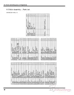
Page 71: ...9 0 Parts List Sequence of Operations 70 9 10 Hydraulic Power Unit Assembly H 507 Rev E...

Page 72: ...9 0 Parts List Sequence of Operations 71 Hydraulic Power Unit Assembly continued H 507 Rev E...

Page 73: ...9 0 Parts List Sequence of Operations 72 9 11 Manifold Assembly H 516 Sheet 1 Rev C...

Page 74: ...9 0 Parts List Sequence of Operations 73 9 12 Hydraulic Schematic H 516 Sheet 2 Rev B...

Page 75: ...9 0 Parts List Sequence of Operations 74 9 13 Manifold Sub Plate Assembly H 517...

Page 76: ...9 0 Parts List Sequence of Operations 75 9 14 Sequence Check Valve Assembly H 551 Rev A...

Page 77: ...9 0 Parts List Sequence of Operations 76 9 15 Basic Machine Schematic E 2853 Rev C...

Page 78: ...9 0 Parts List Sequence of Operations 77 Basic Machine Schematic continued E 2853 Rev C...

Page 79: ...backgauge information see C below C Backgauge control via keyboard The backgauge glide control on the keyboard is used to manually control the backgauge position The speed of the backgauge motor will...

Page 80: ...9 0 Parts List Sequence of Operations 79 9 17 Cut Button Assembly EE 2851 1...

Page 81: ...9 0 Parts List Sequence of Operations 80 9 18 Control Console Assembly EE 2773 1 Rev C...

Page 82: ...9 0 Parts List Sequence of Operations 81 9 19 Control P C Assembly EE 2807 1...

Page 83: ...9 0 Parts List Sequence of Operations 82 9 20 Power Panel Label S 1781 54 Rev C...

Page 84: ...5 F3 5A T Line lights 12 VDC 5mmx 20mm E 2330 7 F4 3A T Main Hot 230 VAC 13 32 x 1 E 1075 3SB F5 1 2A T 5V logic preset encoder 15v prox T2 Primary x 1 E 889 12 F6 1 25A T 12v 24v Pcb outputs T1 Prim...

Page 85: ...9 0 Parts List Sequence of Operations 84 9 22 Knife Latch Assembly 47568 Rev C...

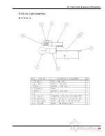
Page 86: ...9 0 Parts List Sequence of Operations 85 9 23 Line Light Assembly EE 2779 Rev B...

Page 87: ...__ ______ ______ ______ ______ Test 2 ______ ______ ______ ______ ______ ______ ______ ______ ______ ______ ______ Date ______ ______ ______ ______ ______ ______ ______ ______ ______ ______ ______ Tes...

Page 88: ...10 0 Safety Systems Test 87 NOTES...

Reviews: