background image

Model EW0820


Installation, Operation, and Maintenance


Page 23 


Rev 2/12/19


EW-IOM-A.doc 

NOTES 


Summary of Contents for EnviroLift EW0820S090

Page 1: ...e EnviroLift MODEL EW0820 8 000 LB CAPACITY 2000 LBS PER ARM 2311 South Park Rd Louisville Kentucky 40219 Email sales challengerlifts com Web site www challengerlifts com Office 800 648 5438 502 625 0700 Fax 502 587 1933 IMPORTANT READ THIS MANUAL COMPLETELY BEFORE INSTALLING or OPERATING LIFT ...

Page 2: ...ructures 84 Lifting Capacity 8 000 lbs 2 000 lbs Per Arm Hydraulic Pressure at Cap 3 480 psi Lifting Time 38 Sec approximate Motor 3HP Single Phase 60Hz 208 230V Shipping Data Lifting Unit Containment Superstructure Pack Power Unit Hardware Box 20 W x95 H x102 L 2120lb 40 W x16 H x48 L 706lb 13 W x13 H x42 L 74lb Lift capacity ratings are based on loads equally distributed on all four arms Lifting...

Page 3: ...Models EW0820 Installation Operation and Maintenance Page 3 Rev 2 12 19 EW IOM A doc Fig 1b General Specifications ...

Page 4: ...th an operating ambient temperature range of 5 40 C 41 104 F ELECTRICAL REQUIREMENTS For lift installation and operation it is necessary to have a dedicated circuit with circuit breaker or time delay fuse Refer to wiring diagram for circuit sizing SAFETY NOTICES AND DECALS For your safety and the safety of others read and understand all of the safety notices and decals included here READ ENTIRE MA...

Page 5: ...IFY Challenger Lifts AT ONCE if any hidden loss or damage is discovered after receipt IT IS DIFFICULT TO COLLECT FOR LOSS OR DAMAGE AFTER YOU HAVE GIVEN THE CARRIER A CLEAR RECEIPT File your claim with Challenger Lifts promptly Support your claim with copies of the bill of lading freight bill and photographs if available The EW0820Challenger Lift consists of three packages the Lift Containment Ass...

Page 6: ...unit to a fitting in the center of the tub The length of hose needed to run from the chase to the fitting is 50inches L 6 25 cu yards of Concrete as the backfill ACCEPTED OILS Do not use oils with detergents Hydraulic fluid is not provided with the lift shipment a 10 wt anti foam anti rust hydraulic biodegradable oil b Dexron III ATF Location Locate lift to allow plenty of working room on all side...

Page 7: ...y determined center lines Refer to Fig 2 and 3 3 Remove the outer two bolts from each end of the protective cover plate and replace with M16 2 0 x 45cm 18 threaded rods see Fig 4 and 5 Lock the threaded rod into the lift with a M16 2 0 jam nut Attach two 6 x 6 timbers using M16 2 0 nuts and washers to support the lift containment assembly on the existing floor Remove the shipping straps and replac...

Page 8: ...t of the flooring While taking care not to run concrete on top of the lift containment assembly pour the remainder of the concrete See Note and Fig 8 Note The floor should slope away from the lift for drainage The floor slope should not exceed 1 16 per foot 3000 psi concrete steel reinforced per local commercial practice is required The new concrete must be mechanically joined to the existing floo...

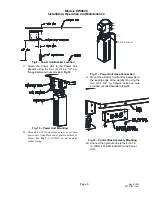
Page 9: ... 9 16 18 O ring elbow in hardware box into power unit Attach free end of power unit hose to elbow See Fig 7 CAUTION do not damage rubber O ring O RING ELBOW Fig 11 Power Unit Hose Connection 19 Mount the 3 Button Control Box Assembly to the leading edge of the workbench using the two 3 8 x 3 4 Lg flanged bolts and nuts provided or suited hardware Fig 12 Fig 12 Control Box Assembly Mounting 20 Conn...

Page 10: ...inder allow the trapped air to escape and tighten bleeder screw Bleed both cylinders until clear oil is seen Refer to Fig 15 Fig 15 Cylinder Bleeding 25 Lower the lift completely and fill the reservoir with 10 weight anti foam anti rust hydraulic oil or Dexron III ATF Do Not Use Oils with Detergents 26 Raise the lift to full stroke and continue to run the power unit for another 10 seconds to check...

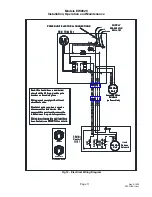
Page 11: ... 208 240 VAC 60Hz 1Ø 4 5 1 2 3 L1 L2 Ground M Black Blue White Brown Grn Yel White Grn Yel Black 2 T1 1 L1 3 A1 4 A2 LOAD INPUT S1 S2 S3 White Black UP DOWN LOCK RELEASE Lock Release Solenoid 240 VAC Coil 3 Button Control 17151 Brown L1 RAISE L2 LOWER GROUND 4 5 1 2 3 Black Red White Orange Green PLUG PINS RECEPTACLE PLUG WIRING LEGEND Each lift should have a dedicated circuit with a 30 Amp double...

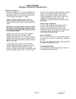
Page 12: ... on the 3 button controller and hold until the vehicles tires just clear the floor STOP and check adapters for proper contact of vehicle manufacturers recommended lifting points and stability of the vehicle Continue to raise the vehicle to a few inches above the desired working height Lower the lift by depressing the lowering button on the 3 button controller until the lock is engaged DO NOT go un...

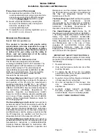
Page 13: ...t in accordance with the lift manufacturer s instructions or ANSI ALI ALOIM 2008 American National Standard for Automotive Lifts Safety Requirements for Operation Inspection and Maintenance and the employer shall insure that the lift inspectors are qualified and that they are adequately trained in the inspection of the lift The Owner Employer shall establish procedures to periodically maintain the...

Page 14: ...nd debris from plunger and bearing wiper by wiping them down with a clean cloth Check for loose or broken parts Monthly Check fluid level in the power unit Check for proper torque on all superstructure bolts 428 ft lbs Clean and lubricate lifting arm pins and pads Quarterly Note The auto greaser will grease the bearings if properly maintained by replacing the auto greaser yearly If Auto Grease Has...

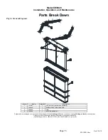
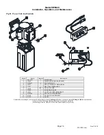
Page 15: ... Assembly 2 106543 1 SUPERSTRUCTURE PACKAGE 3 202320 1 TUB 4 105060 1 AUTO GREASER KIT Replace all worn damaged or broken parts with parts approved by Challenger Lifts Inc or with parts meeting Challenger Lifts Inc specifications Contact your local Challenger Lifts Parts Distributor for pricing and availability Call Challenger Lifts Inc 502 625 0700 for the Parts Distributor in your area ...

Page 16: ...OL BOX 6 16166 25FT 1 4 x 25 AIR LINE 7 37033 1 WORM GEAR CLAMP 8 16164 1 1 4 NPT x 1 4 TUBE UNION ADAPT 9 4100342 4 5 16 x 1 2 LG FLANGED BOLT 10 A1153 2 3 8 x 3 4 LG FLANGED BOLT 11 A1154 2 3 8 NUT Replace all worn damaged or broken parts with parts approved by Challenger Lifts Inc or with parts meeting Challenger Lifts Inc specifications Contact your local Challenger Lifts Parts Distributor for...

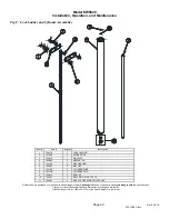
Page 17: ...IVEL ARM RESTRAINT PIN 4 103069 4 SCREW PAD ASSEMBLY 5 103990 8 M24x60 HEX SOCKET HEAD CAP SCREW 6 104238 4 SPRING PIN 5mm D x 15mm L Replace all worn damaged or broken parts with parts approved by Challenger Lifts Inc or with parts meeting Challenger Lifts Inc specifications Contact your local Challenger Lifts Parts Distributor for pricing and availability Call Challenger Lifts Inc 502 625 0700 f...

Page 18: ...8 STRAIGHT ADAPTOR FITTING 6F42EDMXS 9 107278 2 2574 01 FLOW CONTROLLER 6L MIN G1 4 10 103080 1 LOCKING RELEASE UNIT 11 103973 1 M12 X 20 CYLINDER SCREW 12 103977 8 M20 X 50 CYLINDER SCREW 13 102833 1 SYCHRONIZER BEAM ASSEMBLY 14 CAL014 10FT 6mm X 1mm POLY TUBING 15 17131 1 TUBE UNION 1 4 x 6mm Replace all worn damaged or broken parts with parts approved by Challenger Lifts Inc or with parts meeti...

Page 19: ... 5 104712 2 STRAIGHT COUPLING 6 101590 2 SEAL PLUG SCREW 7 103976 12 M16X40 HEX SOCKET HEAD CAP SCREW 8 8 8 104519 12 HEX CAP 9 102813 2 BEARING AND WIPER ASSEMBLY Replace all worn damaged or broken parts with parts approved by Challenger Lifts Inc or with parts meeting Challenger Lifts Inc specifications Contact your local Challenger Lifts Parts Distributor for pricing and availability Call Chall...

Page 20: ... 6 104837 4 M20 NUT 7 102786 2 CYLINDER TUBE 8 103148 2 CYLINDER ROD 9 102814 2 SEAL KIT 10 104207 2 SEAL RING A10 X 16 X 1 5 11 103997 2 M10 X 16 HEX SOCKET HEAD CAP Replace all worn damaged or broken parts with parts approved by Challenger Lifts Inc or with parts meeting Challenger Lifts Inc specifications Contact your local Challenger Lifts Parts Distributor for pricing and availability Call Ch...

Page 21: ...Model EW0820 Installation Operation and Maintenance Page 21 Rev 2 12 19 EW IOM A doc NOTES ...

Page 22: ...Model EW0820 Installation Operation and Maintenance Page 22 Rev 2 12 19 EW IOM A doc NOTES ...

Page 23: ...Model EW0820 Installation Operation and Maintenance Page 23 Rev 2 12 19 EW IOM A doc NOTES ...

Reviews: