Models EW0820
Installation, Operation and Maintenance
Page 9
Rev 2/12/19
EW-IOM-A.doc
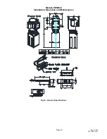
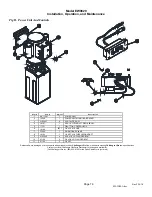
Fig 9 – Power Unit Bracket Location
17.
Attach the Power Unit to the Power Unit
Bracket using the four (4) 5/16 x 1/2" Lg.
flanged bolts and nuts provided,
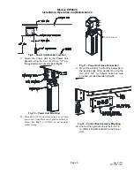
Fig 10
.
Fig. 10 – Power Unit Mounting
18.
Thread 9/16-18 O-ring elbow (
in hardware box
) into
power unit. Attach free end of power unit hose to
elbow. See
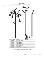
Fig 7.
CAUTION do not damage
rubber O-ring.
'O' RING ELBOW
Fig 11 – Power Unit Hose Connection
19.
Mount the 3-Button Control Box Assembly to
the leading edge of the workbench using the
two
3/8 x 3/4" Lg. flanged bolts and nuts
provided or suited hardware,
Fig 12
.
Fig 12 – Control Box Assembly Mounting
20. Connect the hydraulic line to the 9/16-18
O- RING x 37 DEG ELBOW on the Power
Unit.
Summary of Contents for EnviroLift EW0820S090
Page 21: ...Model EW0820 Installation Operation and Maintenance Page 21 Rev 2 12 19 EW IOM A doc NOTES ...
Page 22: ...Model EW0820 Installation Operation and Maintenance Page 22 Rev 2 12 19 EW IOM A doc NOTES ...
Page 23: ...Model EW0820 Installation Operation and Maintenance Page 23 Rev 2 12 19 EW IOM A doc NOTES ...


