19
B
LEEDING
/S
YNCHRONIZING
21)
After adding fluid to the reservoir, turn
Power on and ensure the Main Switch is
turned to the “ON” position.
22)
Ensure air supply is connected and T-fitting
on runway is plugged or connected to the
rolling jacks with the airline kit.
NOTE:
The
UP
,
DOWN,
LOCK
, and
PHOTOCELL OVERRIDE
switches are
“momentary”, so the function only remains
energized while the button is depressed.
IMPORTANT: DO NOT skip any step.
A
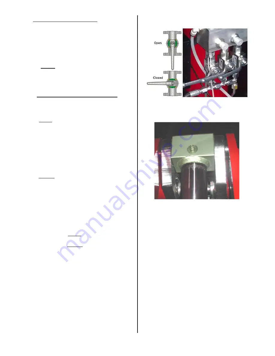
. Ensure all 3 valves are closed,
Fig 8
.
B
. Press
PHOTOCELL OVERRIDE & UP
until both platforms stop moving.*
Note 1
C
. OPEN all 3 valves.
D
. Press
PHOTOCELL OVERRIDE & UP
until both platforms stop moving.
E
. Bleed air from each cylinder,
Fig 9
.
F
. If platforms lower into a lock position,
press
UP
for 5 seconds.
G
. Bleed cylinders until oil begins to escape.
H
. Press
UP
until both platforms stop
moving.
I
. CLOSE all 3 valves.
J
. Press
PHOTOCELL OVERRIDE &
DOWN
.*
Notes 2,3
K
. Repeat entire procedure.*
Note 4
Note 1
: If platforms do not rise after pressing
UP
for 30 seconds, continue to step “C” of
procedure.
Note 2
: If platform(s) stop moving while
lowering, OPEN all 3 valves and continue
lowering. Once both pads are completely
lowered, CLOSE all 3 valves and repeat
the entire bleeding procedure.
Note 3
: With platforms completely lowered, add
oil to fill reservoir.
Note 4
: The bleeding procedure should be
performed at least 3 times and repeated
until both platforms are synchronized thru
the complete raising and lowering of the
platforms and no air comes out of either
bleed screw.
Fig. 8 – Valves
Fig. 9 – Bleed Screw
Summary of Contents for SX14
Page 4: ...4 LIFT BASE LAYOUT Fig 2 Base Layout PIT LAYOUT Fig 3 Pit Details...
Page 9: ...9...
Page 10: ...10 CONTROL UNIT 34 5 16 3 17 4 2 28 14 12 27 26 26 29 31 30 35...
Page 11: ...11 LABEL 2 LABEL 2A LABEL 3 LABEL 3A LABEL 4 LABEL 4A LABEL 5 LABEL 5A...
Page 12: ...12 LABEL 12 LABEL 14 LABEL 14A LABEL 16 LABEL 17...
Page 13: ...13 LABEL 22 LABEL 23 LABEL 25 LABEL 26 LABEL 27 LABEL 28 CHALLENGER SERIAL TAG LABEL 29...
Page 14: ...14 LABEL 30 LABEL 31 LABEL 34 LABEL 35 LABEL 35A...
Page 22: ...22 AIR SWITCH BASE SETTING...
Page 26: ...26 LUBRICATION POINTS repeat symmetrically on both sides of the lift...
Page 30: ...30 Fig 13 Electrical Wiring Diagram Console Lid Switches...
Page 31: ...31 Fig 13 Electrical Wiring Diagram Continued...
Page 32: ...32 Fig 14 Hydraulic Diagram...
Page 33: ...33 Fig 15 Pneumatic Diagram...
Page 34: ...34 PARTS BREAKDOWN 11 16 10 12 10 9 7 8 6 5 2 1 4 3 13 12 15 14...
Page 36: ...36 7 12 14 5 3 4 16 6 10 9 11 15 8 17 17 13 18 2 19 20 21 1 350 BAR 110 BAR...
Page 38: ...38 1 4 5 9 11 12 18 15 13 20 23 22 21 24 6 2 14 25 16 26 3 8 3 7 10...
Page 40: ...40 26 42 24 44 43 47 48 49 50 25 42 43 27 28 30 31 32 29...
Page 42: ...42...
Page 44: ...44 29 48 47 21...


