23
P
HOTOCELL
NORMAL STATUS
GREEN
LED:
ON
YELLOW
LED:
ON
STOP STATUS
GREEN
LED:
ON
YELLOW
LED:
OFF
POSITIONING CHECK
Place an object above reflector and move downwards
check when the YELLOW LED is switched off.
mark the position.
place an object below reflector and move upwards
check when the YELLOW LED is switched off.
mark the position.
the work field is between the two marks.
adjust photocell so work field is centered on Reflector.
Functioning test
Interrupt “photocell beam” using an object and check:
A
With vehicle lift stopped
The lift can be not activated from the control panel
B
With vehicle lift moving
The lift movement stops
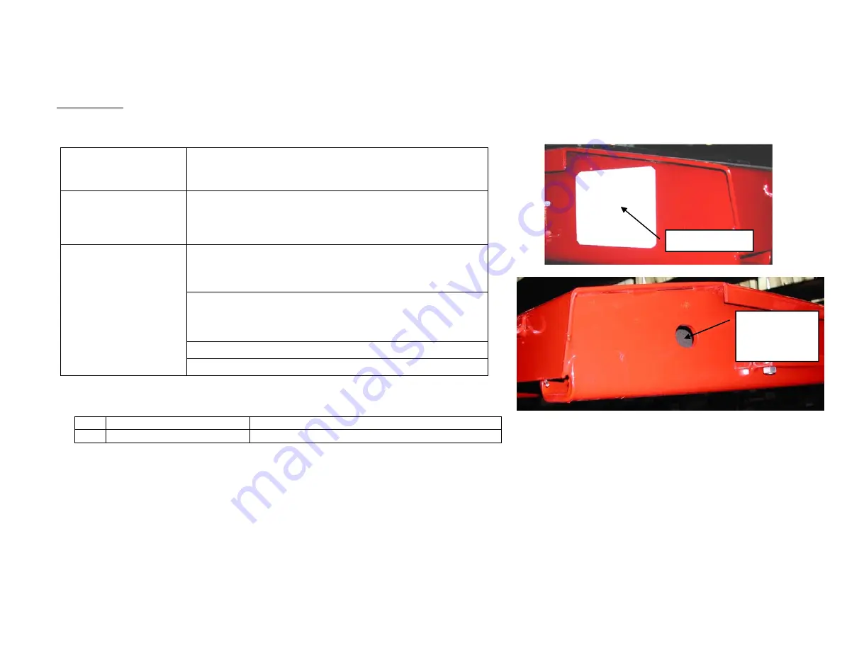
REFLECTOR
PHOTOCELL
Summary of Contents for SX14
Page 4: ...4 LIFT BASE LAYOUT Fig 2 Base Layout PIT LAYOUT Fig 3 Pit Details...
Page 9: ...9...
Page 10: ...10 CONTROL UNIT 34 5 16 3 17 4 2 28 14 12 27 26 26 29 31 30 35...
Page 11: ...11 LABEL 2 LABEL 2A LABEL 3 LABEL 3A LABEL 4 LABEL 4A LABEL 5 LABEL 5A...
Page 12: ...12 LABEL 12 LABEL 14 LABEL 14A LABEL 16 LABEL 17...
Page 13: ...13 LABEL 22 LABEL 23 LABEL 25 LABEL 26 LABEL 27 LABEL 28 CHALLENGER SERIAL TAG LABEL 29...
Page 14: ...14 LABEL 30 LABEL 31 LABEL 34 LABEL 35 LABEL 35A...
Page 22: ...22 AIR SWITCH BASE SETTING...
Page 26: ...26 LUBRICATION POINTS repeat symmetrically on both sides of the lift...
Page 30: ...30 Fig 13 Electrical Wiring Diagram Console Lid Switches...
Page 31: ...31 Fig 13 Electrical Wiring Diagram Continued...
Page 32: ...32 Fig 14 Hydraulic Diagram...
Page 33: ...33 Fig 15 Pneumatic Diagram...
Page 34: ...34 PARTS BREAKDOWN 11 16 10 12 10 9 7 8 6 5 2 1 4 3 13 12 15 14...
Page 36: ...36 7 12 14 5 3 4 16 6 10 9 11 15 8 17 17 13 18 2 19 20 21 1 350 BAR 110 BAR...
Page 38: ...38 1 4 5 9 11 12 18 15 13 20 23 22 21 24 6 2 14 25 16 26 3 8 3 7 10...
Page 40: ...40 26 42 24 44 43 47 48 49 50 25 42 43 27 28 30 31 32 29...
Page 42: ...42...
Page 44: ...44 29 48 47 21...


